Content .. 1296 1297 1298 1299 ..
Nissan Frontier. Manual - part 1298
VTL-14
< REMOVAL AND INSTALLATION >
HEATER & COOLING UNIT ASSEMBLY
HEATER & COOLING UNIT ASSEMBLY
Component
INFOID:0000000009478817
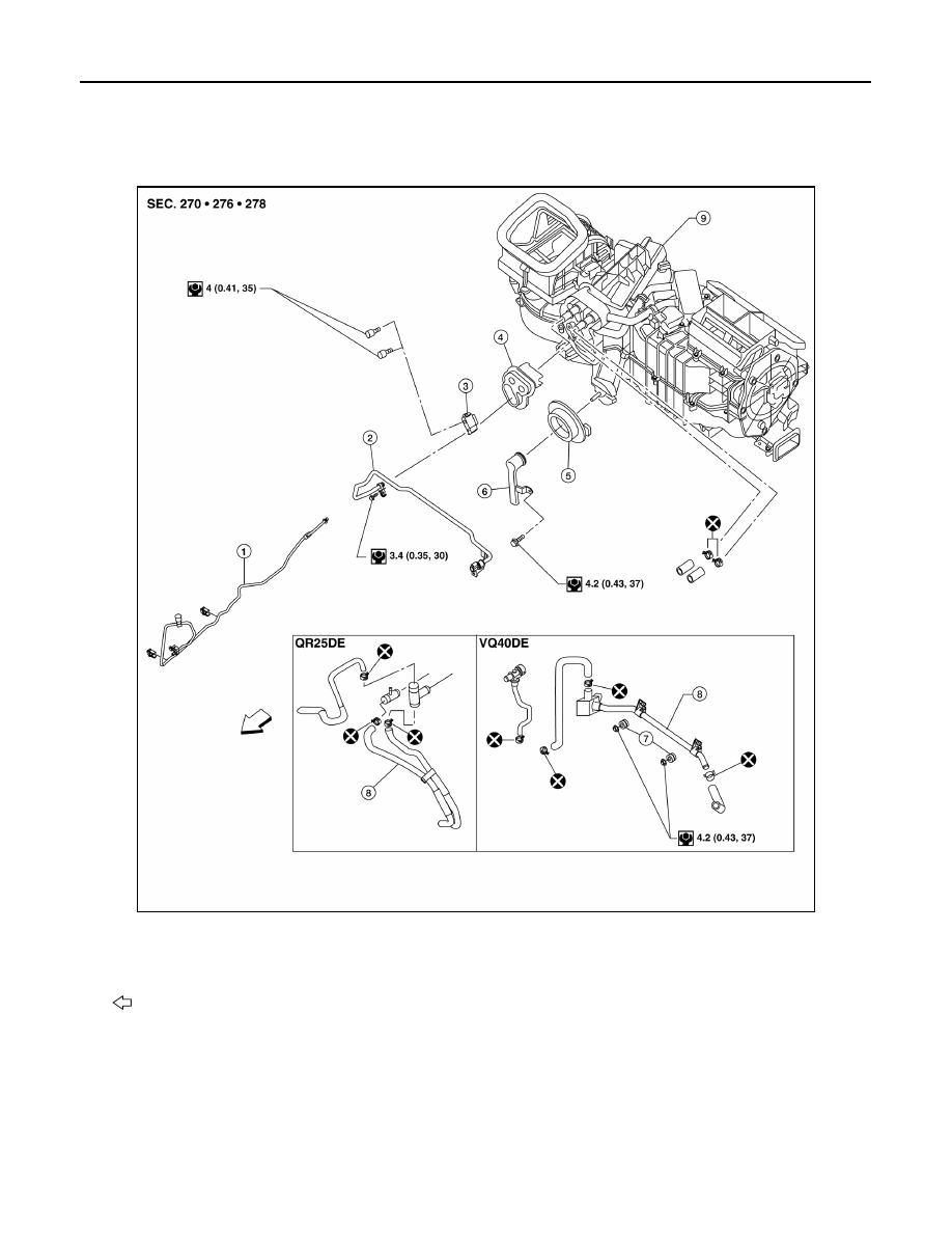
Heater and Cooling Unit Assembly
NOTE:
When removing components such as hoses, tubes/lines, etc., cap or plug openings to prevent fluid from spill-
ing.
Removal and Installation
INFOID:0000000009478818
REMOVAL
CAUTION:
AWIIA1532GB
1.
High-pressure A/C pipe
2.
Low-pressure A/C pipe
3. Expansion valve
4.
Heater core and evaporator pipes grommet
5.
A/C drain hose grommet
6. A/C drain hose
7.
Heater core pipe mounts
8.
Heater core pipes
9. Heater and cooling unit assembly
Front