Nissan Frontier. Manual - part 1280


  Index      Nissan     Nissan Frontier (2014 year) - Service and Repair Manual


Search            


Content   ..  1278  1279  1280  1281   ..


Nissan Frontier. Manual - part 1280


DISASSEMBLY

TM-331

< UNIT DISASSEMBLY AND ASSEMBLY >

[5AT: RE5R05A]

C

E

F

G

H

I

J

K

L

M

A

B

TM

N

O

P

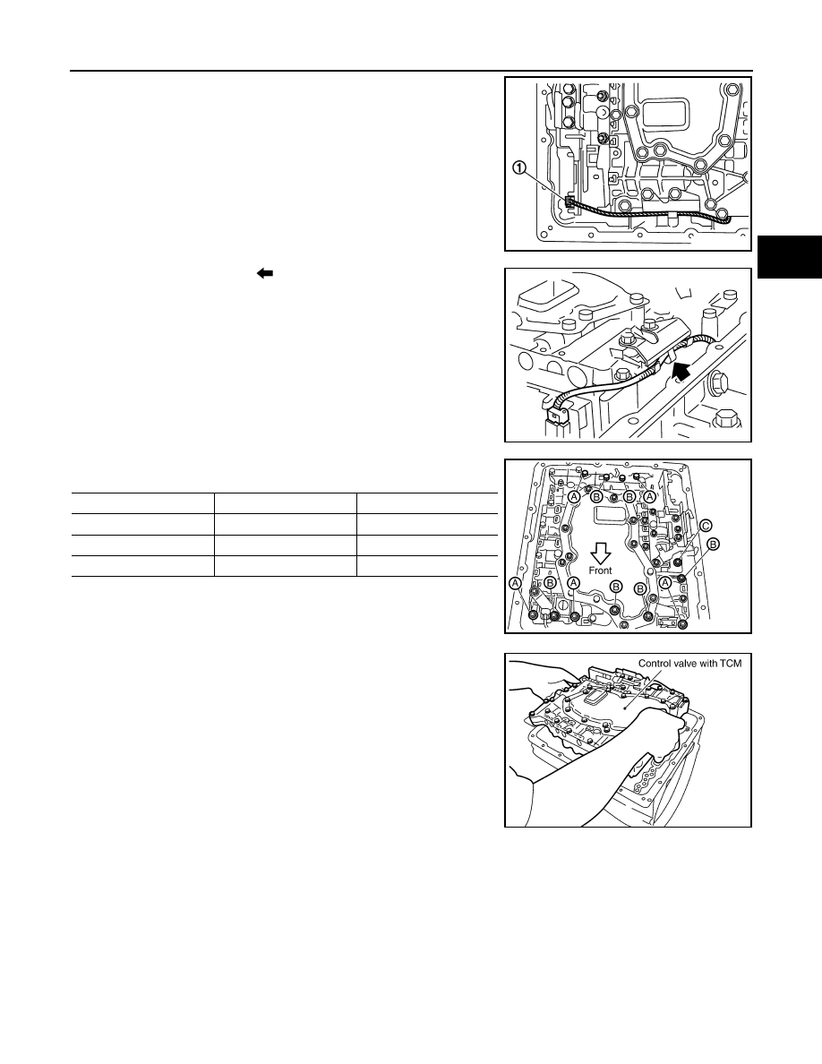
32. Disconnect output speed sensor connector (1).

CAUTION:

Do not damage connector.

33. Straighten terminal clip (

) to free output speed sensor har-

ness.

34. Remove bolts (A), (B) and (C) from control valve with TCM.

35. Remove control valve with TCM from transmission case.

CAUTION:

When removing, be careful with the manual valve notch and

manual plate height. Remove it vertically.

36. Remove the A/T fluid temperature sensor 2 or plug as shown below.
a. A/T fluid temperature sensor 2

JSDIA1319ZZ

JSDIA1320ZZ

Bolt symbol

Length mm (in)

Number of bolts

A

42 (1.65)

5

B

55 (2.17)

6

C

40 (1.57)

1

SCIA5025E

SCIA5260E

TM-332

< UNIT DISASSEMBLY AND ASSEMBLY >

[5AT: RE5R05A]

DISASSEMBLY

i.

Remove A/T fluid temperature sensor 2 with bracket from con-

trol valve with TCM.

ii.

Remove bracket from A/T fluid temperature sensor 2.

b. Plug
i.

Remove plug (1) with bracket (2) from control valve with TCM.

ii.

Remove bracket (1) from plug (2).

SCIA5253E

SCIA5264E

JSDIA1311ZZ

JSDIA1312ZZ

DISASSEMBLY

TM-333

< UNIT DISASSEMBLY AND ASSEMBLY >

[5AT: RE5R05A]

C

E

F

G

H

I

J

K

L

M

A

B

TM

N

O

P

iii. Remove O-ring (1) from plug (2).

CAUTION:

Do not reuse O-ring.

37. Remove O-ring from A/T assembly harness connector.

CAUTION:

Do not reuse O-ring.

38. Disconnect TCM connectors.

CAUTION:

Do not damage connectors.

39. Remove A/T assembly harness connector from control valve

with TCM using suitable tool.

40. Disconnect TCM connector (1) and transmission range switch

connector (2).

CAUTION:

Do not damage connectors.

JSDIA1313ZZ

SCIA5155E

SCIA5447E

SCIA5448E

JSDIA1317ZZ

TM-334

< UNIT DISASSEMBLY AND ASSEMBLY >

[5AT: RE5R05A]

DISASSEMBLY

41. Remove rear extension assembly (2WD models) or adapter case assembly (4WD models) according to

the following procedures.

a. 2WD models
i.

Remove tightening bolts for rear extension assembly and trans-

mission case.

• Bracket (1)

• Bracket (2)

• Self-sealing bolts (3)

• Bolt  (A)

ii.

Tap rear extension assembly with soft hammer.

iii. Remove rear extension assembly (with needle bearing) from

transmission case.

JSDIA0293ZZ

SCIA5028E

SCIA5029E


Content   ..  1278  1279  1280  1281   ..