Nissan Frontier. Manual - part 1279


  Index      Nissan     Nissan Frontier (2014 year) - Service and Repair Manual


Search            


Content   ..  1277  1278  1279  1280   ..


Nissan Frontier. Manual - part 1279


DISASSEMBLY

TM-327

< UNIT DISASSEMBLY AND ASSEMBLY >

[5AT: RE5R05A]

C

E

F

G

H

I

J

K

L

M

A

B

TM

N

O

P

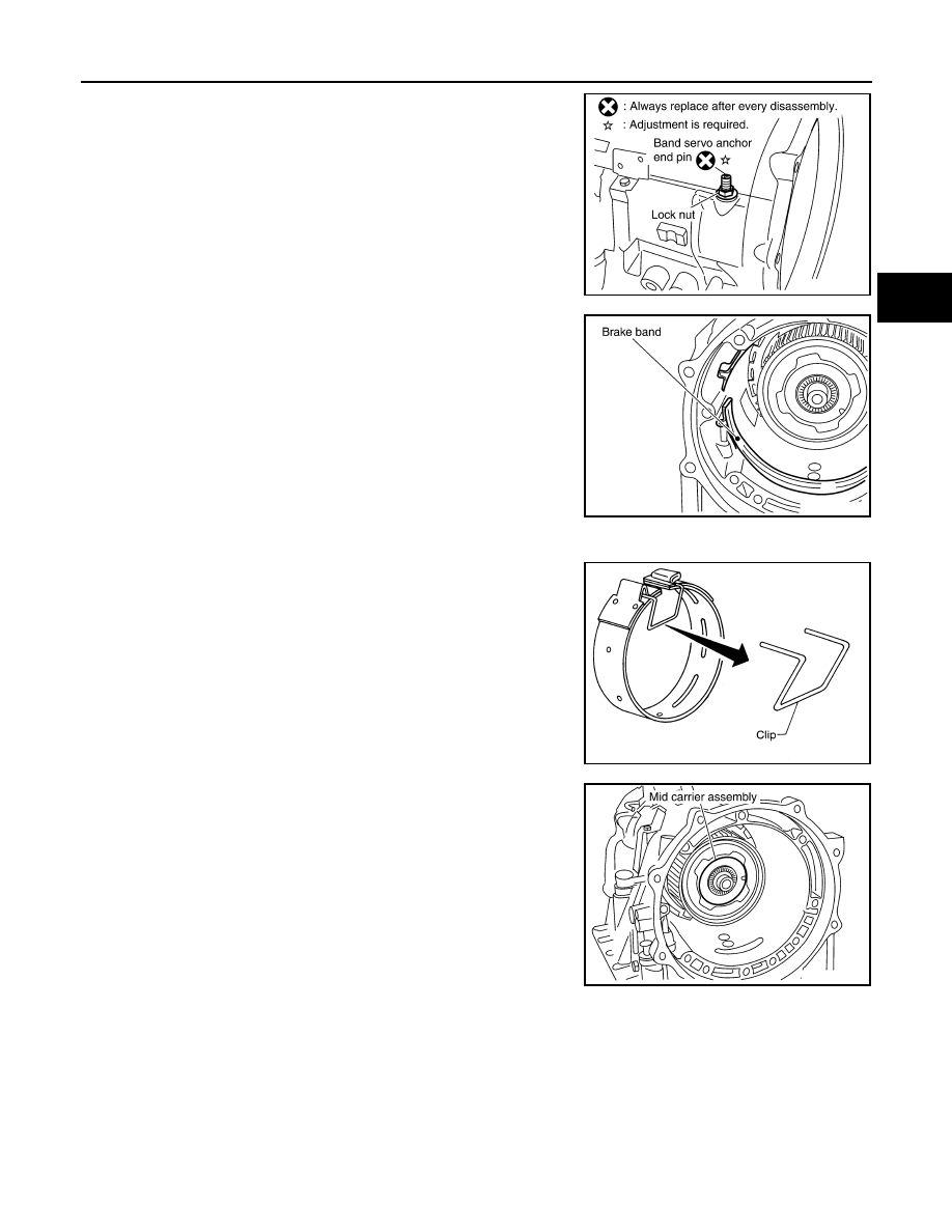
14. Loosen lock nut and remove band servo anchor end pin from

transmission case.

15. Remove brake band from transmission case.

CAUTION:

• To prevent brake linings from cracking or peeling, do not

stretch the flexible band unnecessarily. When removing

the brake band, always secure it with a clip as shown.

• Check brake band facing for damage, cracks, wear or

burns.

16. Remove mid carrier assembly and rear carrier assembly as a

unit.

SCIA6512E

SCIA2580E

SAT655

SCIA5017E

TM-328

< UNIT DISASSEMBLY AND ASSEMBLY >

[5AT: RE5R05A]

DISASSEMBLY

17. Remove mid carrier assembly from rear carrier assembly.

18. Remove needle bearing (front side) from mid carrier assembly.

19. Remove needle bearing (rear side) from mid carrier assembly.

20. Remove bearing race from rear carrier assembly.

21. Remove needle bearing from rear carrier assembly.

SCIA5697E

SCIA2805E

SCIA2804E

SCIA5175E

SCIA2803E

DISASSEMBLY

TM-329

< UNIT DISASSEMBLY AND ASSEMBLY >

[5AT: RE5R05A]

C

E

F

G

H

I

J

K

L

M

A

B

TM

N

O

P

22. Remove mid sun gear assembly, rear sun gear assembly and

high and low reverse clutch hub as a unit.

CAUTION:

Remove them with bearing race and needle bearing.

23. Remove high and low reverse clutch assembly from direct clutch

assembly.

CAUTION:

Make sure that needle bearing is installed to the high and

low reverse clutch assembly edge surface.

24. Remove needle bearing from drum support.

25. Remove direct clutch assembly from reverse brake.

26. Remove snap ring from A/T assembly harness connector.

SCIA5018E

SCIA2306E

SCIA5198E

SCIA5019E

SCIA5021E

TM-330

< UNIT DISASSEMBLY AND ASSEMBLY >

[5AT: RE5R05A]

DISASSEMBLY

27. Push A/T assembly harness connector.

CAUTION:

Do not damage connector.

28. Remove oil pan and oil pan gasket. Refer to 

TM-286, "Removal and Installation"

.

29. Check foreign materials in oil pan to help determine causes of

malfunction. If the A/T fluid is very dark, smells burned, or con-

tains foreign particles, the frictional material (clutches, band)

may need replacement. A tacky film that will not wipe clean indi-

cates varnish build up. Varnish can cause valves, servo, and

clutches to stick and can inhibit pump pressure.

• If frictional material is detected, perform A/T fluid cooler

cleaning. Refer to 

TM-272, "A/T Fluid Cooler Cleaning"

.

30. Remove magnets from oil pan.

31. If an A/T fluid temperature sensor 2 is attached, disconnect the A/T fluid temperature sensor 2 connector

as shown below.

a. Disconnect A/T fluid temperature sensor 2 connector (A).

CAUTION:

Do not damage connector.

b. Straighten terminal clips (

) to free terminal cord assembly and

A/T fluid temperature sensor 2 harness.

SCIA5022E

SCIA5199E

SCIA5200E

SCIA8124E


Content   ..  1277  1278  1279  1280   ..