Nissan Frontier. Manual - part 1275


  Index      Nissan     Nissan Frontier (2014 year) - Service and Repair Manual


Search            


Content   ..  1273  1274  1275  1276   ..


Nissan Frontier. Manual - part 1275


TRANSMISSION ASSEMBLY

TM-311

< UNIT REMOVAL AND INSTALLATION >

[5AT: RE5R05A]

C

E

F

G

H

I

J

K

L

M

A

B

TM

N

O

P

10. Remove the starter motor.
11. Remove the front and rear propeller shafts. Refer to 

DLN-134, "Removal and Installation"

 (2F1310), 

DLN-

143, "Removal and Installation"

 (2S1330) or (3S1330-2BJ100) 

DLN-174, "Removal and Installation"

.

12. Remove the left and right front exhaust tubes. Refer to 

EX-6, "Removal and Installation"

.

13. Remove the shift selector control cable and bracket from the A/T.
14. Disconnect the fluid cooler tubes from the A/T assembly.

CAUTION:

Do not reuse copper sealing washers.

15. Remove the dust cover from the converter housing.
16. Turn the crankshaft to access and remove the four bolts for the

drive plate and torque converter.

CAUTION:

When turning the crankshaft, turn it clockwise as viewed

from the front of the engine.

17. Support the A/T assembly using a transmission jack.

CAUTION:

When setting the transmission jack, be careful not to allow

it to collide against the drain plug.

18. Remove the nuts securing the insulator to the crossmember.
19. Remove the crossmember using power tool.
20. Tilt the transmission slightly to gain clearance between the body and the transmission, then disconnect

the air breather hose.

21. Disconnect the following:

• A/T assembly harness connector

• 4LO switch harness connector

• Wait detection switch harness connector

• ATP switch harness connector

• Transfer control device harness connector

22. Remove the wiring harness from the retainers.
23. Remove the A/T fluid indicator pipe.
24. Remove the A/T assembly to engine bolts using power tool.
25. Remove A/T assembly with transfer from the vehicle using Tool.

CAUTION:

• Secure the torque converter to prevent it from dropping.

• Secure the A/T assembly to a transmission jack.

NOTE:

The actual special service Tool may differ from Tool shown.

26. Remove the transfer from the A/T assembly. Refer to 
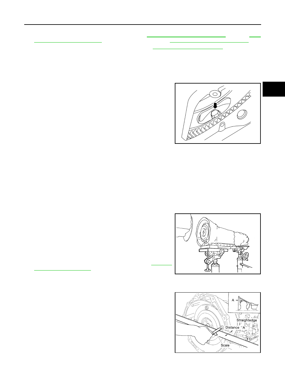
DLN-101,

"Removal and Installation"

.

INSPECTION

Installation and Inspection of Torque Converter

• After inserting a torque converter to a transmission, be sure to

check dimension (A) to ensure it is within the reference value limit.

Tool number

:

 (J-47002)

LCIA0335E

SCIA2203E

Dimension (A)

: 25.0 mm (0.98 in) or more

SAT017B

TM-312

< UNIT REMOVAL AND INSTALLATION >

[5AT: RE5R05A]

TRANSMISSION ASSEMBLY

INSTALLATION

Installation of the remaining components is in the reverse order of removal, while paying attention to the fol-

lowing.

• When installing transmission to the engine, tighten the bolts to the

specified torque using sequence shown.

• Align the positions of bolts for drive plate with those of the torque

converter, and temporarily tighten the bolts. Then, tighten the bolts

with the specified torque.

CAUTION:

• When turning crankshaft, turn it clockwise as viewed from the

front of the engine.

• After converter is installed to drive plate, rotate crankshaft

several turns and check to be sure that transmission rotates

freely without binding.

• When replacing an engine or transmission you must make

sure the dowels are installed correctly during re-assembly.

• Improper alignment caused by missing dowels may cause

vibration, oil leaks or breakage of drive train components.

• Install crankshaft position sensor (POS). 

• After completing installation, check fluid leakage, fluid level, and the positions of A/T. Refer to 

TM-269,

"Checking the A/T Fluid (ATF)"

TM-285, "Inspection and Adjustment"

.

Transmission bolts

: 75 N·m (7.6 kg-m, 55 ft-lb)

LCIA0370E

LCIA0335E

OVERHAUL

TM-313

< UNIT DISASSEMBLY AND ASSEMBLY >

[5AT: RE5R05A]

C

E

F

G

H

I

J

K

L

M

A

B

TM

N

O

P

UNIT DISASSEMBLY AND ASSEMBLY

OVERHAUL

Exploded View

INFOID:0000000009480692

SCIA7040E

TM-314

< UNIT DISASSEMBLY AND ASSEMBLY >

[5AT: RE5R05A]

OVERHAUL

1.

O-ring

2.

Oil pump cover

3.

O-ring

4.

Oil pump housing

5.

Self-sealing bolt

6.

Torque converter

7.

Converter housing

8.

Oil pump housing oil seal

9.

Bearing race

10. Needle bearing

11. O-ring

12. Front carrier assembly

13. Needle bearing

14. Snap ring

15. Front sun gear

16. 3rd one-way clutch

17. Snap ring

18. Bearing race

19. Needle bearing

20. Seal ring

21. Input clutch assembly

22. Needle bearing

23. Rear internal gear

24. Brake band

25. Mid carrier assembly

26. Needle bearing 

27. Bearing race

28. Rear carrier assembly

29. Needle bearing 

30. Mid sun gear

31. Seal ring

32. Rear sun gear

33. 1st one-way clutch

34. Snap ring

35. Needle bearing

36. High and low reverse clutch hub

37. Snap ring

38. Bearing race

39. Needle bearing

: Apply Genuine RTV silicone sealant or equivalent. Refer to 

GI-21, "Recommended Chemical Products and Sealants"

.

Refer to 

GI-4, "Component"

 for symbols not described on the above.


Content   ..  1273  1274  1275  1276   ..