Content .. 1271 1272 1273 1274 ..
Nissan Frontier. Manual - part 1273
A/T FLUID COOLER
TM-303
< REMOVAL AND INSTALLATION >
[5AT: RE5R05A]
C
E
F
G
H
I
J
K
L
M
A
B
TM
N
O
P
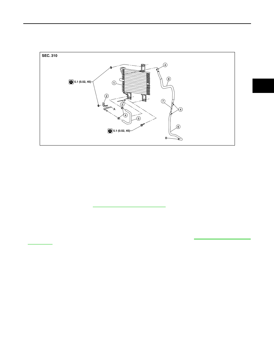
A/T FLUID COOLER
Removal and Installation
INFOID:0000000009480687
NOTE:
When removing components such as hoses, tubes/lines, etc., cap or plug openings to prevent fluid from spill-
ing.
REMOVAL
1. Remove front grille. Refer to
EXT-23, "Removal and Installation"
2. Remove A/T fluid cooler hoses from fluid cooler.
3. Remove A/T fluid cooler.
INSTALLATION
Installation is in the reverse order of removal.
• After completing installation, check fluid level and check for fluid leaks. Refer to
1.
A/T fluid cooler
2.
Fluid cooler tube
3.
Clip
4.
Hose clamp
5.
Cooler hose (lower)
6.
Cooler hose
7.
Tube joint
8.
Cooler hose (upper)
A.
To transmission
B.
From radiator
AWDIA0631GB