Content .. 1068 1069 1070 1071 ..
Nissan Frontier. Manual - part 1070
PWC-12
< DTC/CIRCUIT DIAGNOSIS >
POWER SUPPLY AND GROUND CIRCUIT
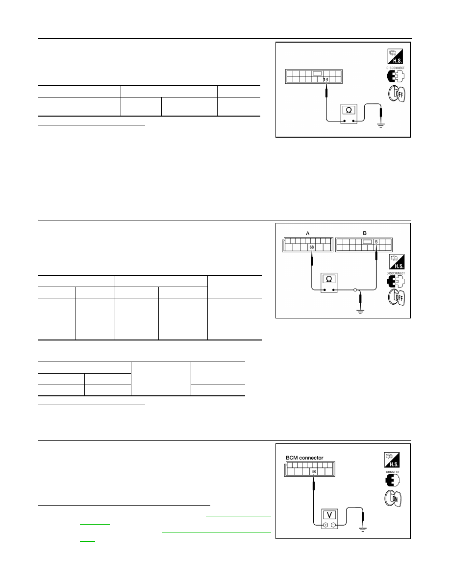
1. Turn ignition switch OFF.
2. Disconnect main power window and door lock/unlock switch.
3. Check continuity between main power window and door lock/
unlock switch connector D7 terminal 14 and ground.
Is the inspection result normal?
YES
>> Check main power window and door lock/unlock switch
output signal (rear power window switch LH) GO TO 5
YES
>> Check main power window and door lock/unlock switch output signal (rear power window switch
RH) GO TO 6
YES
>> Check main power window and door lock/unlock switch output signal (front power window switch
RH) GO TO 7
YES
>> Check main power window and door lock/unlock switch output signal (front power window switch
LH) GO TO 8
NO
>> Repair or replace harness.
3.
CHECK MAIN POWER WINDOW AND DOOR LOCK/UNLOCK SWITCH POWER SUPPLY CIRCUIT
1. Turn ignition switch OFF.
2. Disconnect BCM and main power window and door lock/unlock
switch.
3. Check continuity between BCM and main power window and
door lock/unlock switch.
4. Check continuity between BCM and ground.
Is the inspection result normal?
YES
>> GO TO 4
NO
>> Repair or replace harness.
4.
CHECK BCM OUTPUT SIGNAL
1. Connect BCM.
2. Turn ignition switch ON.
3. Check voltage between BCM connector M20 terminal 68 and
ground.
Is the measurement value within the specification?
YES
>> Check intermittent incident. Refer to
NO
BCS-49, "Removal and Installa-
.
5.
CHECK MAIN POWER WINDOW AND DOOR LOCK/UNLOCK SWITCH OUTPUT SIGNAL (REAR POW-
Connector
Terminals
Continuity
Main power window and
door lock/unlock switch: D7
14
Ground
Yes
LIIA2188E
A
B
Continuity
Connector
Terminal
Connector
Terminal
BCM: M20
68
Main power
window and
door lock/un-
lock switch:
D7
5
Yes
A
Ground
Continuity
Connector
Terminal
BCM: M20
68
No
LIIA2165E
68 - Ground
: Battery voltage
LIIA2055E