Content .. 1069 1070 1071 1072 ..
Nissan Frontier. Manual - part 1071
PWC-16
< DTC/CIRCUIT DIAGNOSIS >
POWER SUPPLY AND GROUND CIRCUIT
Is the inspection result normal?
YES
>> Main power window and door lock/unlock switch is OK.
NO
>> Replace main power window and door lock/unlock switch. Refer to
.
POWER WINDOW MAIN SWITCH (KING CAB)
POWER WINDOW MAIN SWITCH (KING CAB) : Description
INFOID:0000000009482389
• BCM supplies power.
• It operates each power window motor via corresponding power window switch and makes window move up/
down when main power window and door lock/unlock switch is operated.
POWER WINDOW MAIN SWITCH (KING CAB) : Component Function Check
INFOID:0000000009482390
Main Power Window And Door Lock/Unlock Switch
1.
CHECK MAIN POWER WINDOW AND DOOR LOCK/UNLOCK SWITCH FUNCTION
Check power window motor operation with main power window and door lock/unlock switch.
Is the inspection result normal?
YES
>> Main power window and door lock/unlock switch power supply and ground circuit are OK.
NO
>> Refer to
PWC-16, "POWER WINDOW MAIN SWITCH (KING CAB) : Diagnosis Procedure"
POWER WINDOW MAIN SWITCH (KING CAB) : Diagnosis Procedure
INFOID:0000000009482391
Regarding Wiring Diagram information, refer to
PWC-48, "Wiring Diagram - King Cab"
.
1.
CHECK POWER SUPPLY CIRCUIT
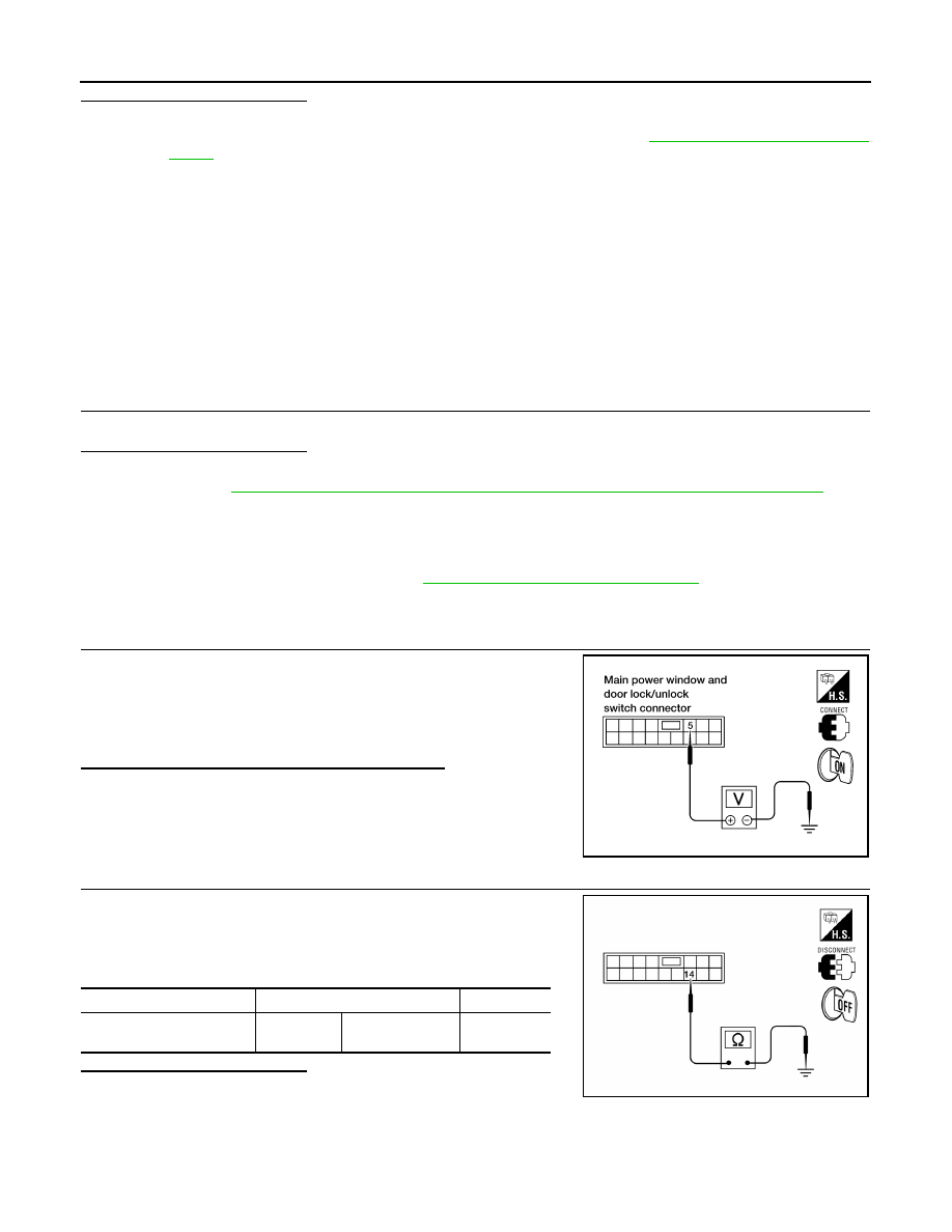
1. Turn ignition switch ON.
2. Check voltage between main power window and door lock/
unlock switch connector D7 terminal 5 and ground.
Is the measurement value within the specification?
YES
>> GO TO 2
NO
>> GO TO 3
2.
CHECK GROUND CIRCUIT
1. Turn ignition switch OFF.
2. Disconnect main power window and door lock/unlock switch.
3. Check continuity between main power window and door lock/
unlock switch connector D7 terminal 14 and ground.
Is the inspection result normal?
YES
>> Check main power window and door lock/unlock switch
output signal (front power window switch RH) GO TO 5
YES
>> Check main power window and door lock/unlock switch output signal (front power window switch
LH) GO TO 6
NO
>> Repair or replace harness.
5 - Ground
: Battery voltage
LIIA1703E
Connector
Terminals
Continuity
Main power window and
door lock/unlock switch: D7
14
Ground
Yes
LIIA2188E