Nissan Frontier. Manual - part 1023


  Index      Nissan     Nissan Frontier (2014 year) - Service and Repair Manual


Search            


Content   ..  1021  1022  1023  1024   ..


Nissan Frontier. Manual - part 1023


MWI-36

< DTC/CIRCUIT DIAGNOSIS >

FUEL LEVEL SENSOR SIGNAL CIRCUIT

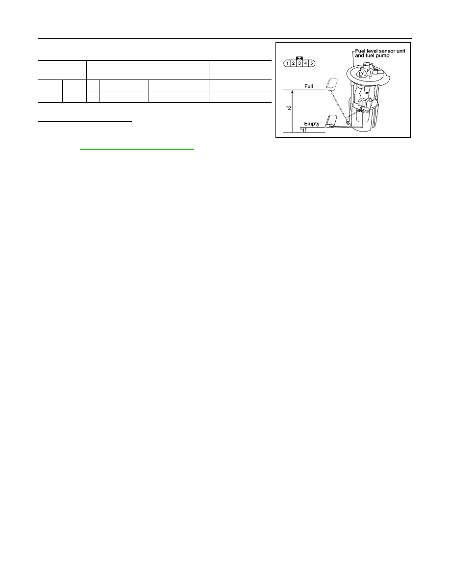
Check the resistance between terminals 2 and 5.

*1 and *2: When float arm is in contact with stopper.

Is inspection result normal?

YES

>> Inspection End.

NO

>> Replace fuel level sensor unit and fuel pump. Refer to

FL-10, "Removal and Installation"

.

Terminal

Float position

mm (in)

Resistance value

(Approx.)

2

5

*1

Empty

10 (0.4)

81.5

*2

Full

211.1 (8.3)

5

LKIA0402E

MWI

OIL PRESSURE SWITCH SIGNAL CIRCUIT

MWI-37

< DTC/CIRCUIT DIAGNOSIS >

C

D

E

F

G

H

I

J

K

L

M

B

A

O

P

OIL PRESSURE SWITCH  SIGNAL CIRCUIT

Description

INFOID:0000000009480368

Detects the engine oil pressure and transmits the oil pressure switch signal to the IPDM E/R.

Component Function Check

INFOID:0000000009480369

1.

COMBINATION METER INPUT SIGNAL

1. Select “METER/M&A” on CONSULT.

2. Monitor “OIL W/L” of “DATA MONITOR” while operating ignition switch.

>> Inspection End.

Diagnosis Procedure

INFOID:0000000009480370

Regarding Wiring Diagram information, refer to 

MWI-65, "Wiring Diagram"

.

1.

CHECK OIL PRESSURE SWITCH CIRCUIT

1. Turn ignition switch OFF.

2. Disconnect IPDM E/R connector E122 and oil pressure switch

connector E208 (VQ40DE) or F4 (QR25DE).

3. Check continuity between IPDM E/R harness connector E122

(A) terminal 42 and oil pressure switch harness connector E208

(VQ40DE) or F4 (QR25DE) (B) terminal 1.

Is the inspection result normal?

YES

>> Inspection End.

NO

>> Repair harness or connector.

Component Inspection

INFOID:0000000009480371

1.

CHECK OIL PRESSURE SWITCH

Check continuity between oil pressure switch and ground.

Is the inspection result normal?

YES

>> Inspection End.

NO

>> Replace the oil pressure switch.

OIL W/L
When ignition switch is in ON 
position (Engine stopped)

: ON

When engine is running

: OFF

Continuity should exist.

WKIA5607E

Condition

Oil pressure [kPa (kg/cm

2

, psi)]

Continuity

Engine stopped

Less than 29 (0.3, 4)

Yes

Engine running

More than 29 (0.3, 4) 

No

ELF0044D

MWI-38

< ECU DIAGNOSIS INFORMATION >

COMBINATION METER

ECU DIAGNOSIS INFORMATION

COMBINATION METER

Reference Value

INFOID:0000000009480372

TERMINAL LAYOUT

PHYSICAL VALUES

LKIA0698E

Termi-

nal

Wire 

color

Item

Condition

Reference value (V)

(Approx.)

Ignition 

switch

Operation or condition

2

P

Generator

ON

Generator voltage low

0

Generator voltage normal

Battery voltage

3

R/Y

Battery power supply

Battery voltage

4

B/Y

Fuel level sensor ground

ON

0

5

W

Vehicle speed signal out-
put (2-pulse)

ON

Speedometer operated
[When vehicle speed is ap-
prox. 20 km/h (12 MPH)]

240 Hz

6

SB

Vehicle speed signal out-
put (8-pulse)

ON

Speedometer operated
[When vehicle speed is ap-
prox. 40 km/h (25 MPH)]

NOTE:
Maximum voltage may be 12V due to spec-
ifications (connected units).

7

G

Transmission ragne sig-
nal

ON

Shift lever: P or N

0

Shift lever: Except above

Battery voltage

9

BR

Fuel level sensor signal

Refer to 

MWI-12, "FUEL GAUGE : System 

Description"

.

11

P

CAN-L

12

L

CAN-H

13

GR

Ground

0

16

W/G

Ignition switch ON or 
START

ON

Battery voltage

17

B

AT-PN switch

18

L

AT 1 Range switch

20

Y

O/D off switch

ON

O/D off switch ON

0

O/D off switch OFF

Battery voltage

22

BR

Illumination control 
switch

Refer to 

INL-74, "System Description"

.

PKIC0643E

MWI

COMBINATION METER

MWI-39

< ECU DIAGNOSIS INFORMATION >

C

D

E

F

G

H

I

J

K

L

M

B

A

O

P

Fail Safe

INFOID:0000000009480373

The combination meter performs a fail-safe operation for the functions listed below when communication is

lost.

23

B

Ground

0

24

V

Seat belt buckle switch 
LH

ON

Unfastened (ON)

0

Fastened (OFF)

Battery voltage

25

SB

DIFF LOCK indicator in-
put

ON

DIFF LOCK indicator ON

0

DIFF LOCK indicator OFF

Battery voltage

31

G

Parking brake switch

ON

Parking brake applied

0

Parking brake released

Battery voltage

32

SB

Brake fluid level switch

ON

Brake fluid level low

0

Brake fluid level normal

Battery voltage

34

L

Washer fluid level switch

ON

Washer fluid level low

0

Washer fluid level normal

Battery voltage

37

SB

Air bag warning lamp in-
put

ON

Air bag warning lamp ON

4

Air bag warning lamp OFF

0

39

G

Security indicator input

OFF

Security indicator ON

0

Security indicator OFF

Battery voltage

40

LG

Seat belt buckle switch 
RH

ON

Unfastened (ON)

0

Fastened (OFF)

Battery voltage

Termi-

nal

Wire 

color

Item

Condition

Reference value (V)

(Approx.)

Ignition 

switch

Operation or condition

Function

Specifications

Speedometer

Zero indication.

Tachometer

Fuel gauge

Engine coolant temperature gauge

Engine oil pressure gauge (with 6 gauge combination meter)

Voltage gauge (with 6 gauge combination meter)

Illumination control

Meter illumination

Change to nighttime mode when communication is lost.

Segment LCD

Odometer

Freeze current indication.

A/T position

Display turns off.

Buzzer

Buzzer turns off.


Content   ..  1021  1022  1023  1024   ..