Content .. 1020 1021 1022 1023 ..
Nissan Frontier. Manual - part 1022
MWI-32
< DTC/CIRCUIT DIAGNOSIS >
POWER SUPPLY AND GROUND CIRCUIT
BCM (BODY CONTROL MODULE) : Diagnosis Procedure
INFOID:0000000010217857
Regarding Wiring Diagram information, refer to
.
1.
CHECK FUSES AND FUSIBLE LINK
Check that the following fuses and fusible link are not blown.
Is the fuse blown?
YES
>> Replace the blown fuse or fusible link after repairing the affected circuit.
NO
>> GO TO 2
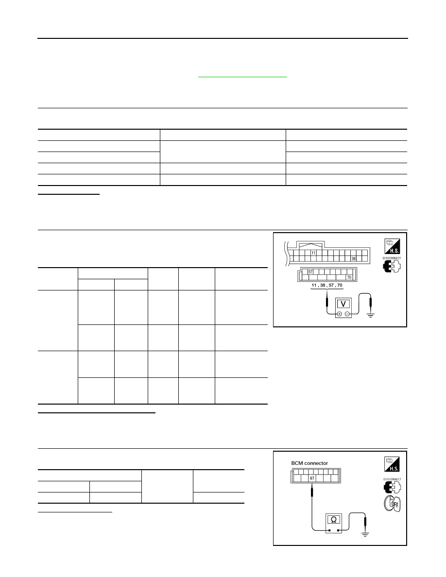
2.
CHECK POWER SUPPLY CIRCUIT
1. Turn ignition switch OFF.
2. Disconnect BCM.
3. Check voltage between BCM harness connector and ground.
Is the measurement value normal?
YES
>> GO TO 3
NO
>> Repair or replace harness.
3.
CHECK GROUND CIRCUIT
Check continuity between BCM harness connector and ground.
Does continuity exist?
YES
>> Inspection End.
NO
>> Repair or replace harness.
IPDM E/R (INTELLIGENT POWER DISTRIBUTION MODULE ENGINE ROOM)
Terminal No.
Signal name
Fuses and fusible link No.
57
Battery power supply
21 (10A)
70
G (50A)
11
Ignition ACC or ON
4 (10A)
38
Ignition ON or START
1 (10A)
Connector
Terminals
Power
source
Condition
Voltage (V) (Ap-
prox.)
(+)
(-)
M18
11
Ground
ACC
power
supply
Ignition
switch
ACC or
ON
Battery voltage
38
Ground
Ignition
power
supply
Ignition
switch ON
or START
Battery voltage
M20
57
Ground
Battery
power
supply
Ignition
switch
OFF
Battery voltage
70
Ground
Battery
power
supply
Ignition
switch
OFF
Battery voltage
LIIA2415E
BCM
Ground
Continuity
Connector
Terminal
M20
67
Yes
LIIA0915E