Nissan Frontier. Manual - part 1018


  Index      Nissan     Nissan Frontier (2014 year) - Service and Repair Manual


Search            


Content   ..  1016  1017  1018  1019   ..


Nissan Frontier. Manual - part 1018


MWI-16

< SYSTEM DESCRIPTION >

METER SYSTEM

VOLTAGE GAUGE : Component Description

INFOID:0000000009480336
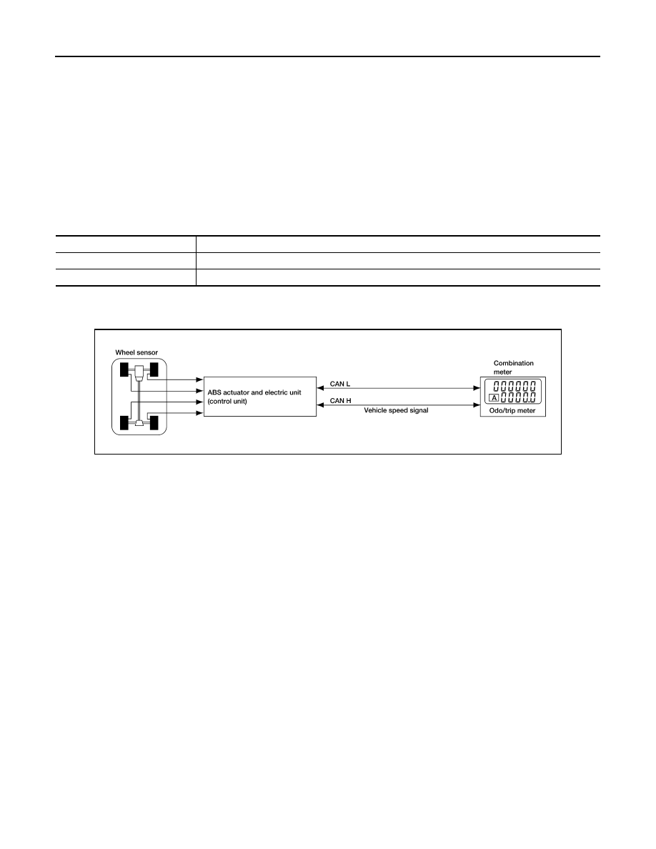
ODO/TRIP METER
ODO/TRIP METER : System Diagram

INFOID:0000000009480337

ODO/TRIP METER : System Description

INFOID:0000000009480338

The vehicle speed signal and the memory signals from the meter memory circuit are processed by the combi-

nation meter and the mileage is displayed.

LOOSE FUEL CAP WARNING

The LOOSE FUEL CAP indicator will display in the odometer when the fuel-filler cap is not tightened correctly.

The indicator will turn off as soon as the ECM detects the fuel-filler cap is properly tightened.  The ECM pro-

vides a loose fuel cap signal to the combination meter via CAN communication lines.

CHECK TIRE PRESSURE WARNING

The CHECK TIRE PRESSURE indicator will display in the odometer when BCM has detected a low tire pres-

sure condition.

HOW TO CHANGE THE DISPLAY FOR ODO/TRIP METER

Refer to Owner's Manual for odo/trip meter operating instructions.

1.

Combination meter M24

2.

Fuel level sensor unit and fuel pump C5 
(view with fuel tank removed)

3.

ECM (view with ECM cover removed)
E8 (with VQ40DE for Mexico)
E16 (with QR25DE)
E55 (with VQ40DE except Mexico)
A. Coolant reservoir

4.

ABS actuator and electric unit (control 
unit) E127

5.

Oil pressure switch E208 (with VQ40DE)
A. Oil pan (upper)

6.

Oil pressure switch F4 (with 
QR25DE) (view with engine re-
moved)

7.

A/T assembly F9 (with A/T)

8.

BCM M18, M19 (view with lower instru-
ment panel LH removed)

9.

IPDM E/R E122, E124

Unit

Description

Combination meter

Indicates the battery voltage according to the voltage signal received from the fuse block (J/B).

Fuse block (J/B)

Transmits the battery voltage signal to the combination meter.

AWNIA0005GB

MWI

METER SYSTEM

MWI-17

< SYSTEM DESCRIPTION >

C

D

E

F

G

H

I

J

K

L

M

B

A

O

P

ODO/TRIP METER : Component Parts Location

INFOID:0000000009480339

ODO/TRIP METER : Component Description

INFOID:0000000009480340

SHIFT POSITION INDICATOR

AWNIA0781ZZ

1.

Combination meter M24

2.

Fuel level sensor unit and fuel pump C5 
(view with fuel tank removed)

3.

ECM (view with ECM cover removed)
E8 (with VQ40DE for Mexico)
E16 (with QR25DE)
E55 (with VQ40DE except Mexico)
A. Coolant reservoir

4.

ABS actuator and electric unit (control 
unit) E127

5.

Oil pressure switch E208 (with VQ40DE)
A. Oil pan (upper)

6.

Oil pressure switch F4 (with 
QR25DE) (view with engine re-
moved)

7.

A/T assembly F9 (with A/T)

8.

BCM M18, M19 (view with lower instru-
ment panel LH removed)

9.

IPDM E/R E122, E124

Unit

Description

Combination meter

Converts the vehicle speed signal received from the ABS actuator and electric unit (control unit) via 
CAN communication to mileage, and it displays the accumulated mileage to the odo/trip meter. 

ABS actuator and electric unit
(control unit)

Transmits the vehicle speed signal to the combination meter via CAN communication. 

MWI-18

< SYSTEM DESCRIPTION >

METER SYSTEM

SHIFT POSITION INDICATOR : System Diagram

INFOID:0000000009480341

SHIFT POSITION INDICATOR : System Description

INFOID:0000000009480342

The TCM receives A/T indicator signals from the transmission range switch. The TCM then sends A/T position

indicator signals to the combination meter via CAN communication lines. The combination meter indicates the

received shift position.

SHIFT POSITION INDICATOR : Component Parts Location

INFOID:0000000009480343

AWNIA3309GB

AWNIA0781ZZ

1.

Combination meter M24

2.

Fuel level sensor unit and fuel pump C5 
(view with fuel tank removed)

3.

ECM (view with ECM cover removed)
E8 (with VQ40DE for Mexico)
E16 (with QR25DE)
E55 (with VQ40DE except Mexico)
A. Coolant reservoir

4.

ABS actuator and electric unit (control 
unit) E127

5.

Oil pressure switch E208 (with VQ40DE)
A. Oil pan (upper)

6.

Oil pressure switch F4 (with 
QR25DE) (view with engine re-
moved)

7.

A/T assembly F9 (with A/T)

8.

BCM M18, M19 (view with lower instru-
ment panel LH removed)

9.

IPDM E/R E122, E124

MWI

METER SYSTEM

MWI-19

< SYSTEM DESCRIPTION >

C

D

E

F

G

H

I

J

K

L

M

B

A

O

P

SHIFT POSITION INDICATOR : Component Description

INFOID:0000000009480344

WARNING LAMPS/INDICATOR LAMPS
WARNING LAMPS/INDICATOR LAMPS : System Diagram

INFOID:0000000009480345

WARNING LAMPS/INDICATOR LAMPS : System Description

INFOID:0000000009480346

OIL PRESSURE WARNING LAMP

• IPDM E/R reads the ON/OFF signals from the oil pressure switch and transmits the oil pressure switch sig-

nal to the combination meter via BCM with the CAN communication line. 

• The combination meter turns the oil pressure warning lamp ON/OFF according to the oil pressure switch sig-

nal received via CAN communication. 

WARNING LAMPS/INDICATOR LAMPS : Component Parts Location

INFOID:0000000009480347

Unit

Description

Combination meter

Displays the shift position using shift position signal received from TCM.

TCM

Transmits the shift position signal to the combination meter via CAN communication. 

JSNIA0449GB

AWNIA0781ZZ


Content   ..  1016  1017  1018  1019   ..