Content .. 1017 1018 1019 1020 ..
Nissan Frontier. Manual - part 1019
MWI-20
< SYSTEM DESCRIPTION >
METER SYSTEM
WARNING LAMPS/INDICATOR LAMPS : Component Description
INFOID:0000000009480348
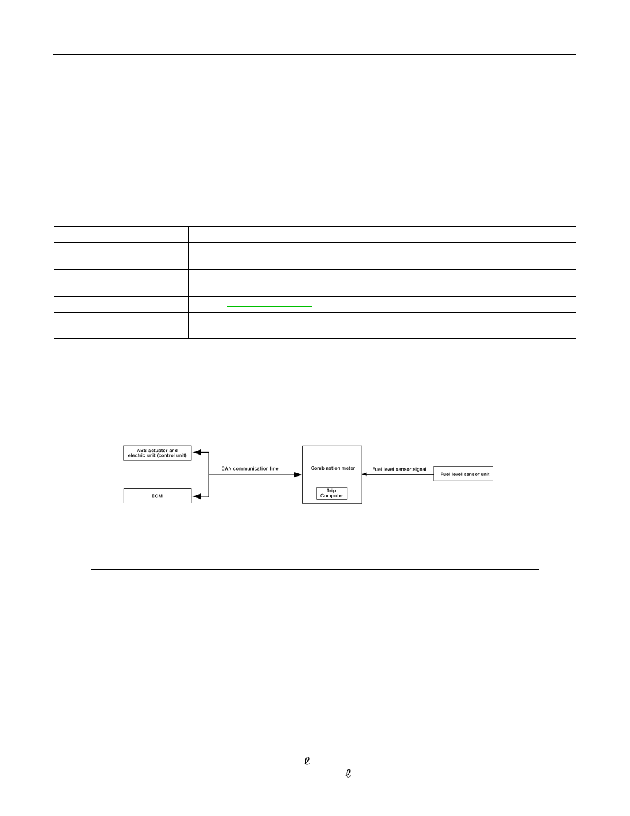
TRIP COMPUTER
TRIP COMPUTER : System Diagram
INFOID:0000000009480349
TRIP COMPUTER : System Description
INFOID:0000000009480350
FUNCTION
The trip computer can indicate the following items.
• DTE (distance to empty)
• Trip distance
• Trip time
• Average fuel consumption
• Average vehicle speed
DTE (DISTANCE TO EMPTY) INDICATION
The range indication provides the driver with an estimation of the distance that can be driven before refueling.
The range is calculated by signals from the fuel level sensor unit (fuel remaining), ECM (fuel consumption)
and the ABS actuator and electric unit (vehicle speed). The indication will be refreshed every 30 seconds.
When fuel remaining is less than approximately 11.6 (3 1/8 US gal, 2 1/2 Imp gal), the indication will blink as
a warning. If the fuel remaining is less than approximately 9.6 (2 1/2 US gal, 2 1/8 Imp gal), the indication will
1.
Combination meter M24
2.
Fuel level sensor unit and fuel pump C5
(view with fuel tank removed)
3.
ECM (view with ECM cover removed)
E8 (with VQ40DE for Mexico)
E16 (with QR25DE)
E55 (with VQ40DE except Mexico)
A. Coolant reservoir
4.
ABS actuator and electric unit (control
unit) E127
5.
Oil pressure switch E208 (with VQ40DE)
A. Oil pan (upper)
6.
Oil pressure switch F4 (with
QR25DE) (view with engine re-
moved)
7.
A/T assembly F9 (with A/T)
8.
BCM M18, M19 (view with lower instru-
ment panel LH removed)
9.
IPDM E/R E122, E124
Unit
Description
Combination meter
Turns the oil pressure warning lamp ON/OFF according to the oil pressure switch signal received
from BCM by means of communication.
IPDM E/R
Reads the ON/OFF signals from the oil pressure switch and transmits the oil pressure switch signal
to the combination meter via BCM with the CAN communication line.
Oil pressure switch
Refer to
.
BCM
Transmits the oil pressure switch signal received from IPDM E/R via CAN communication to the
combination meter via CAN communication.
AWNIA0218GB