Nissan Sentra. Manual - part 913


  Index      Nissan     Nissan Sentra (2014 year) - Service and Repair Manual


Search            


Content   ..  911  912  913  914   ..


Nissan Sentra. Manual - part 913


TM-288

< SERVICE DATA AND SPECIFICATIONS (SDS) 

[CVT: RE0F11A]

SERVICE DATA AND SPECIFICATIONS (SDS)

SERVICE DATA AND SPECIFICATIONS (SDS)

SERVICE DATA AND SPECIFICATIONS (SDS)

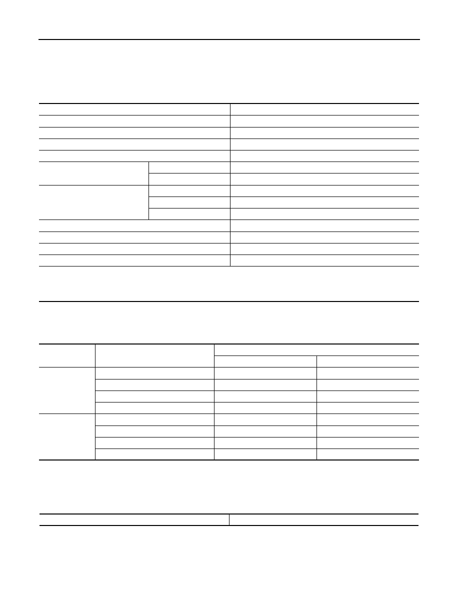
General Specification

INFOID:0000000009759541

*: The CVT fluid capacity is the reference value.

Shift Characteristics

INFOID:0000000009759542

Unit: rpm

NOTE:

Lock-up is engaged at the vehicle speed of approximately 10 km/h (11 MPH) to 90 km/h (56 MPH). 

Stall Speed

INFOID:0000000009759543

Unit: rpm

Engine model

MRA8DE

Drive type

2WD

Transaxle model

RE0F11A

Transaxle model code number

X427A

Stall torque ratio

1.91 : 1

Pulley ratio

Forward

2.200 – 0.550

Reverse

2.200

Auxiliary gearbox gear ratio

1GR

1.821

2GR

1.000

Reverse

1.714

Counter gear

0.906

Final drive

3.882

Recommended fluid

Genuine NISSAN CVT Fluid NS-3

Fluid capacity liter (US qt, lmp qt)

Approx. 6.9 (7-1/4, 6-1/8)*

CAUTION:

• Use only Genuine NISSAN CVT Fluid NS-3. Never mix with other fluid.
• Use only Genuine NISSAN CVT Fluid NS-3. Using transmission fluid other than Genuine NISSAN CVT Fluid NS-3 will dam-

age the CVT, which is not covered by the warranty.

 Throttle position

Shift pattern

CVT input speed

At 40 km/h (25 MPH)

At 60 km/h (37 MPH)

2/8

“D” position (OD ON)

1,500 – 2,600

1,700 – 3,000

“D” position (OD OFF)

2,300 – 3,100

2,700 – 3,500

“L” position

3,000 – 3,800

3,500 – 4,300

ECO mode

1,500 – 2,300

1,700 – 2,500

8/8

“D” position (OD ON)

3,900 – 5,000

4,500 – 6,100

“D” position (OD OFF)

3,900 – 5,000

4,500 – 6,100

“L” position

3,900 – 5,000

4,500 – 6,100

ECO mode

3,900 – 4,700

4,500 – 5,300

Stall speed

2,690 – 3,200

SERVICE DATA AND SPECIFICATIONS (SDS)

TM-289

< SERVICE DATA AND SPECIFICATIONS (SDS) 

[CVT: RE0F11A]

C

E

F

G

H

I

J

K

L

M

A

B

TM

N

O

P

Line Pressure

INFOID:0000000009759544

Unit: MPa (kg/cm

2

, psi)

Torque Converter

INFOID:0000000009759545

Unit: mm (in)

Heater Thermostat

INFOID:0000000009759546

Shift selector position

Engine speed

Line pressure

“P” and “N”

At idle

0.50 (5.1, 72.5)

“R” and “D”

At idle

0.50 (5.1, 72.5) – 1.38 (14.1, 200.1)

At stall

4.19 (42.7, 607.5) – 4.69 (47.8, 680.0)

Dimension between the converter housing and torque converter

14.4 (0.567)

Valve opening temperature

69 – 73

°C (156 –163°F)

Maximum valve lift

5.0 mm/85

°C (0.197 in/185°F)

Valve closing temperature

65

°C (149°F)

VTL-1

VENTILATION, HEATER & AIR CONDITIONER

C

D

E

F

G

H

J

K

L

M

SECTION 

VTL

A

B

VTL

N

O

P

CONTENTS

VENTILATION SYSTEM

PRECAUTION ...............................................

2

PRECAUTIONS ...................................................

2

Precaution for Supplemental Restraint System 
(SRS) "AIR BAG" and "SEAT BELT PRE-TEN-
SIONER" .................................................................
..

2

Precaution for Work  ..................................................

2

PREPARATION ............................................

3

PREPARATION ...................................................

3

Special Service Tool  .................................................

3

Commercial Service Tool  ..........................................

3

PERIODIC MAINTENANCE ..........................

4

IN-CABIN MICROFILTER  ...................................

4

Exploded View  ..........................................................

4

Removal and Installation ...........................................

4

SYSTEM DESCRIPTION  ..............................

5

IN-CABIN MICROFILTER  ...................................

5

Description ................................................................

5

REMOVAL AND INSTALLATION ................

6

DUCTS AND GRILLES  .......................................

6

Exploded View  ..........................................................

6

DEFROSTER NOZZLE ................................................

7

DEFROSTER NOZZLE : Removal and Installation 

......

7

CENTER VENTILATOR DUCT ....................................

7

CENTER VENTILATOR DUCT : Removal and In-
stallation ..................................................................
.

7

SIDE VENTILATOR DUCT  .........................................

7

SIDE VENTILATOR DUCT : Removal and Instal-
lation ........................................................................
.

7

REAR FLOOR DUCT ..................................................

7

REAR FLOOR DUCT : Removal and Installation - 
Rear Floor Connecting Duct  ....................................
.

7

REAR FLOOR DUCT : Removal and Installation - 
Rear Floor Duct  .......................................................
.

7

REAR FLOOR DUCT : Removal and Installation - 
Rear Floor Duct Nozzle  ...........................................
.

8

Exploded View ..........................................................

8

DEFROSTER GRILLE  ................................................

8

DEFROSTER GRILLE : Removal and Installation .....

8

CENTER VENTILATOR GRILLE ................................

9

CENTER VENTILATOR GRILLE : Removal and 
Installation ...............................................................
.

9

SIDE VENTILATOR GRILLE  ......................................

9

SIDE VENTILATOR GRILLE : Removal and In-
stallation ..................................................................
.

9

SIDE DEFROSTER GRILLE .......................................

9

SIDE DEFROSTER GRILLE : Removal and In-
stallation ..................................................................
.

9

BLOWER MOTOR  ............................................

10

Exploded View .........................................................

10

Removal and Installation  .........................................

10

VTL-2

< PRECAUTION >

PRECAUTIONS

PRECAUTION

PRECAUTIONS

Precaution for Supplemental Restraint System (SRS) "AIR BAG" and "SEAT BELT 
PRE-TENSIONER"

INFOID:0000000010288779

The Supplemental Restraint System such as “AIR BAG” and “SEAT BELT PRE-TENSIONER”, used along

with a front seat belt, helps to reduce the risk or severity of injury to the driver and front passenger for certain

types of collision. Information necessary to service the system safely is included in the SR and SB section of

this Service Manual.

WARNING:

• To avoid rendering the SRS inoperative, which could increase the risk of personal injury or death in

the event of a collision which would result in air bag inflation, all maintenance must be performed by

an authorized NISSAN/INFINITI dealer.

• Improper maintenance, including incorrect removal and installation of the SRS, can lead to personal

injury caused by unintentional activation of the system. For removal of Spiral Cable and Air Bag

Module, see the SR section.

• Do not use electrical test equipment on any circuit related to the SRS unless instructed to in this

Service Manual. SRS wiring harnesses can be identified by yellow and/or orange harnesses or har-

ness connectors.

PRECAUTIONS WHEN USING POWER TOOLS (AIR OR ELECTRIC) AND HAMMERS

WARNING:

• When working near the Airbag Diagnosis Sensor Unit or other Airbag System sensors with the Igni-

tion ON or engine running, DO NOT use air or electric power tools or strike near the sensor(s) with a

hammer. Heavy vibration could activate the sensor(s) and deploy the air bag(s), possibly causing

serious injury.

• When using air or electric power tools or hammers, always switch the Ignition OFF, disconnect the

battery and wait at least three minutes before performing any service.

Precaution for Work

INFOID:0000000009758096

• When removing or disassembling each component, be careful not to damage or deform it. If a component

may be subject to interference, be sure to protect it with a shop cloth.

• When removing (disengaging) components with a screwdriver or similar tool, be sure to wrap the component

with a shop cloth or vinyl tape to protect it.

• Protect the removed parts with a shop cloth and prevent them from being dropped.

• Replace a deformed or damaged clip.

• If a part is specified as a non-reusable part, always replace it with a new one.

• Be sure to tighten bolts and nuts securely to the specified torque.

• After installation is complete, be sure to check that each part works properly.

• Follow the steps below to clean components:

- Water soluble dirt:

• Dip a soft cloth into lukewarm water, wring the water out of the cloth and wipe the dirty area.

• Then rub with a soft, dry cloth.

- Oily dirt:

• Dip a soft cloth into lukewarm water with mild detergent (concentration: within 2 to 3%) and wipe the dirty

area.

• Then dip a cloth into fresh water, wring the water out of the cloth and wipe the detergent off.

• Then rub with a soft, dry cloth.

- Do not use organic solvent such as thinner, benzene, alcohol or gasoline.

- For genuine leather seats, use a genuine leather seat cleaner.


Content   ..  911  912  913  914   ..