Nissan Sentra. Manual - part 710
POWER SUPPLY AND GROUND CIRCUIT
PWC-37
< DTC/CIRCUIT DIAGNOSIS >
C
D
E
F
G
H
I
J
L
M
A
B
PWC
N
O
P
Is the inspection result normal?
YES
>> Main power window and door lock/unlock switch is OK.
NO
>> Replace main power window and door lock/unlock switch. Refer to
POWER WINDOW MAIN SWITCH : Special Repair Requirement
INFOID:0000000009757238
1.
PERFORM INITIALIZATION PROCEDURE
Perform initialization procedure.
Is the inspection result normal?
YES
>> GO TO 2.
NO
>> Check intermittent incident. Refer to
GI-39, "Intermittent Incident"
.
2.
CHECK ANTI-PINCH OPERATION
Check anti-pinch operation.
Is the inspection result normal?
YES
>> Inspection End.
NO
>> Refer to
PWC-32, "POWER WINDOW MAIN SWITCH : Component Function Check"
FRONT POWER WINDOW SWITCH
FRONT POWER WINDOW SWITCH : Description
INFOID:0000000009757239
• BCM supplies power.
• Front power window motor RH will be operated if power window and door lock/unlock switch RH is operated.
FRONT POWER WINDOW SWITCH : Component Function Check
INFOID:0000000009757240
Power Window And Door Lock/unlock Switch RH
1.
CHECK POWER WINDOW MOTOR FUNCTION
Check front power window motor operation with power window and door lock/unlock switch RH.
Is the inspection result normal?
YES
>> Power window and door lock/unlock switch RH power supply and ground circuit are OK.
NO
>> Refer to
PWC-37, "FRONT POWER WINDOW SWITCH : Diagnosis Procedure"
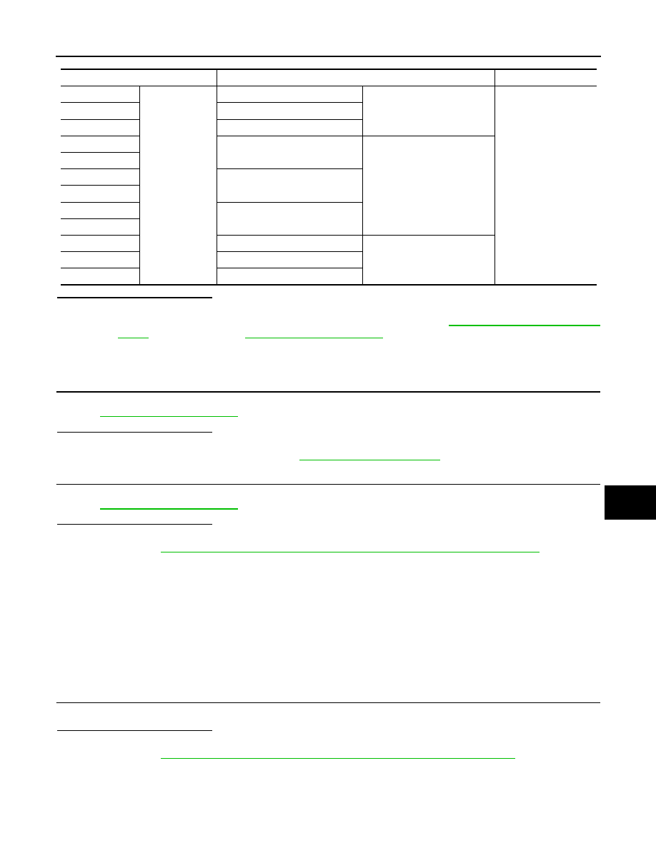
FRONT POWER WINDOW SWITCH : Diagnosis Procedure
INFOID:0000000009757241
Terminal
Main power window and door lock/unlock switch condition
Continuity
9
1
Rear LH
UP
Yes
7
Rear RH
16
Front RH
8
Rear LH
NEUTRAL
9
7
Rear RH
6
2
Front RH
16
8
Rear LH
DOWN
6
Rear RH
2
Front RH