Nissan Sentra. Manual - part 709


  Index      Nissan     Nissan Sentra (2014 year) - Service and Repair Manual


Search            


Content   ..  707  708  709  710   ..


Nissan Sentra. Manual - part 709


POWER SUPPLY AND GROUND CIRCUIT

PWC-33

< DTC/CIRCUIT DIAGNOSIS >

C

D

E

F

G

H

I

J

L

M

A

B

PWC

N

O

P

POWER WINDOW MAIN SWITCH : Diagnosis Procedure

INFOID:0000000009757236

Regarding Wiring Diagram information, refer to 

PWC-18, "Wiring Diagram"

.

Main Power Window And Door Lock/unlock Switch Power Supply Circuit Check

1.

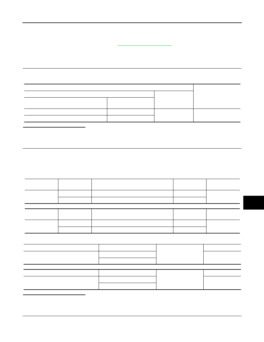
 CHECK POWER SUPPLY CIRCUIT 

1. Turn ignition switch ON.

2. Check voltage between main power window and door lock/unlock switch connectors D5, D11 and ground.

Is the inspection result normal?

YES

>> GO TO 3.

NO

>> GO TO 2.

2.

 CHECK HARNESS CONTINUITY 

1. Turn ignition switch OFF.

2. Disconnect BCM, main power window and door lock/unlock switch, power window and door lock/unlock

switch RH, rear power window switch LH and rear power window switch RH.

3. Check continuity between BCM connector and main power window and door lock/unlock switch connec-

tors.

With Intelligent Key system

Without Intelligent Key system

4. Check continuity between BCM connector M85 or M20 and ground.

With Intelligent Key system

Without Intelligent Key system

Is the inspection result normal?

YES

>> GO TO 4.

NO

>> Repair or replace the harness or connectors.

3.

 CHECK GROUND CIRCUIT

1. Turn ignition switch OFF.

2. Disconnect main power window and door lock/unlock switch.

Terminal

Voltage

(Approx.)

(+)

(–)

Main power window and door lock/unlock switch

Terminal 

D5

10

Ground

Battery voltage

D11

18

BCM

connector

Terminal

Main power window and door lock/unlock switch

connector

Terminal

Continuity

M85

92

D5

10

Yes

91

D11

18

BCM

connector

Terminal

Main power window and door lock/unlock switch

connector

Terminal

Continuity

M20

68

D5

10

Yes

69

D11

18

BCM connector

Terminal

Ground

Continuity

M85

91

No

92

BCM connector

Terminal

Ground

Continuity

M20

68

No

69

PWC-34

< DTC/CIRCUIT DIAGNOSIS >

POWER SUPPLY AND GROUND CIRCUIT

3. Check continuity between main power window and door lock/unlock switch connector D11 and ground.

Is the inspection result normal?

YES

>> Check main power window and door lock/unlock switch output signal (rear power window switch

LH) GO TO 5.

YES

>> Check main power window and door lock/unlock switch output signal (rear power window switch

RH) GO TO 6.

YES

>> Check main power window and door lock/unlock switch output signal (front power window switch

LH) GO TO 7.

YES

>> Check main power window and door lock/unlock switch output signal (front power window switch

RH) GO TO 8.

NO

>> Repair or replace the harness or connectors.

4.

 CHECK BCM OUTPUT SIGNAL 

1. Connect BCM. 

2. Turn ignition switch ON.

3. Check voltage between BCM connector M85 or M20 and ground.

With Intelligent Key system

Without Intelligent Key system

Is the inspection result normal?

YES

>> Check intermittent incident. Refer to 

GI-39, "Intermittent Incident"

.

NO

>> Replace BCM. Refer to 

BCS-73, "Removal and Installation"

 (with Intelligent Key) or 

BCS-126,

"Removal and Installation"

 (without Intelligent Key).

5.

 CHECK MAIN POWER WINDOW AND DOOR LOCK/UNLOCK SWITCH OUTPUT SIGNAL (REAR POW-

ER WINDOW SWITCH LH)
1. Connect main power window and door lock/unlock switch.

2. Turn ignition switch ON.

3. Check voltage between main power window and door lock/unlock switch D5 and ground.

Is the inspection result normal?

YES

>> Check intermittent incident. Refer to 

GI-39, "Intermittent Incident"

.

Main power window and door lock/unlock switch connector

Terminal

Ground

Continuity 

D11

1

Yes

Terminals

Voltage

(Approx.)

(+)

(–)

BCM connector

Terminal 

M85

91

Ground

Battery voltage

92

Terminals

Voltage

(Approx.)

(+)

(–)

BCM connector

Terminal 

M20

68

Ground

Battery voltage

69

Terminal

Window switch

position (rear LH)

Voltage

(Approx.)

(+)

(–)

Main power window and door lock/

unlock switch connector

Terminal 

D5

9

Ground

UP

Battery voltage

DOWN

0

8

UP

0

DOWN

Battery voltage

POWER SUPPLY AND GROUND CIRCUIT

PWC-35

< DTC/CIRCUIT DIAGNOSIS >

C

D

E

F

G

H

I

J

L

M

A

B

PWC

N

O

P

NO

>> Replace main power window and door lock/unlock switch. Refer to 

PWC-70, "Removal and Instal-

lation"

. After that, refer to 

PWC-29, "Work Procedure"

.

6.

 CHECK MAIN POWER WINDOW AND DOOR LOCK/UNLOCK SWITCH OUTPUT SIGNAL (REAR POW-

ER WINDOW SWITCH RH)

1. Connect main power window and door lock/unlock switch.

2. Turn ignition switch ON.

3. Check voltage between main power window and door lock/unlock switch D5 and ground.

Is the inspection result normal?

YES

>> Check intermittent incident. Refer to 

GI-39, "Intermittent Incident"

.

NO

>> Replace main power window and door lock/unlock switch. Refer to 

PWC-70, "Removal and Instal-

lation"

. After that, refer to 

PWC-29, "Work Procedure"

.

7.

 CHECK MAIN POWER WINDOW AND DOOR LOCK/UNLOCK SWITCH OUTPUT SIGNAL (FRONT

POWER WINDOW SWITCH LH)

1. Connect main power window and door lock/unlock switch.

2. Turn ignition switch ON.

3. Check voltage between main power window and door lock/unlock switch D11 and ground.

Is the inspection result normal?

YES

>> Check intermittent incident. Refer to 

GI-39, "Intermittent Incident"

.

NO

>> Replace main power window and door lock/unlock switch. Refer to 

PWC-70, "Removal and Instal-

lation"

. After that, refer to 

PWC-29, "Work Procedure"

.

8.

 CHECK MAIN POWER WINDOW AND DOOR LOCK/UNLOCK SWITCH OUTPUT SIGNAL (FRONT

POWER WINDOW SWITCH RH)

1. Connect main power window and door lock/unlock switch.

2. Turn ignition switch ON.

3. Check voltage between main power window and door lock/unlock switch D5 and ground.

Terminal

Window switch

position (rear RH)

Voltage

(Approx.)

(+)

(–)

Main power window and door 

lock/unlock switch connector

Terminal 

D5

7

Ground

UP

Battery voltage

DOWN

0

6

UP

0

DOWN

Battery voltage

Terminal

Window switch

position (front LH)

Voltage

(Approx.)

(+)

(–)

Main power window and door lock/

unlock switch connector

Terminal 

D11

17

Ground

UP

Battery voltage

DOWN

0

19

UP

0

DOWN

Battery voltage

PWC-36

< DTC/CIRCUIT DIAGNOSIS >

POWER SUPPLY AND GROUND CIRCUIT

Is the inspection result normal?

YES

>> Check intermittent incident. Refer to 

GI-39, "Intermittent Incident"

.

NO

>> Replace main power window and door lock/unlock switch. Refer to 

PWC-70, "Removal and Instal-

lation"

. After that, refer to 

PWC-29, "Work Procedure"

.

POWER WINDOW MAIN SWITCH : Component Inspection

INFOID:0000000009757237

1.

 CHECK MAIN POWER WINDOW AND DOOR LOCK/UNLOCK SWITCH 

1. Check main power window and door lock/unlock switch D5.

2. Check continuity between main power window and door lock/unlock switch D5 (power window lock

switch) (Lock operation).

3. Check continuity between main power window and door lock/unlock switch D5 (power window lock

switch) (Unlock operation).

Terminal

Window switch

position (front RH)

Voltage

(Approx.)

(+)

(–)

Main power window and door 

lock/unlock switch connector

Terminal 

D5

16

Ground

UP

Battery voltage

DOWN

0

2

UP

0

DOWN

Battery voltage

Terminal

Main power window and door lock/unlock switch condition

Continuity

10

9

Rear LH

UP

Yes

10

7

Rear RH

10

16

Front RH

8

9

Rear  LH

NEUTRAL

6

7

 Rear RH

2

16

Front  RH

10

8

Rear LH

DOWN

10

6

 Rear RH

10

2

Front RH

1

12

-

Terminal

Main power window and door lock/unlock switch condition

Continuity

9

1

Rear LH

UP

No

7

Rear  RH

16

Front RH

8

Rear LH

NEUTRAL

9

7

Rear RH

6

2

Front RH

16

8

Rear  LH

DOWN

6

Rear  RH

2

Front  RH


Content   ..  707  708  709  710   ..