Nissan Sentra. Manual - part 630


  Index      Nissan     Nissan Sentra (2014 year) - Service and Repair Manual


Search            


Content   ..  628  629  630  631   ..


Nissan Sentra. Manual - part 630


CHASSIS AND BODY MAINTENANCE

MA-23

< PERIODIC MAINTENANCE >

C

D

E

F

G

H

I

J

K

L

M

B

MA

N

O

A

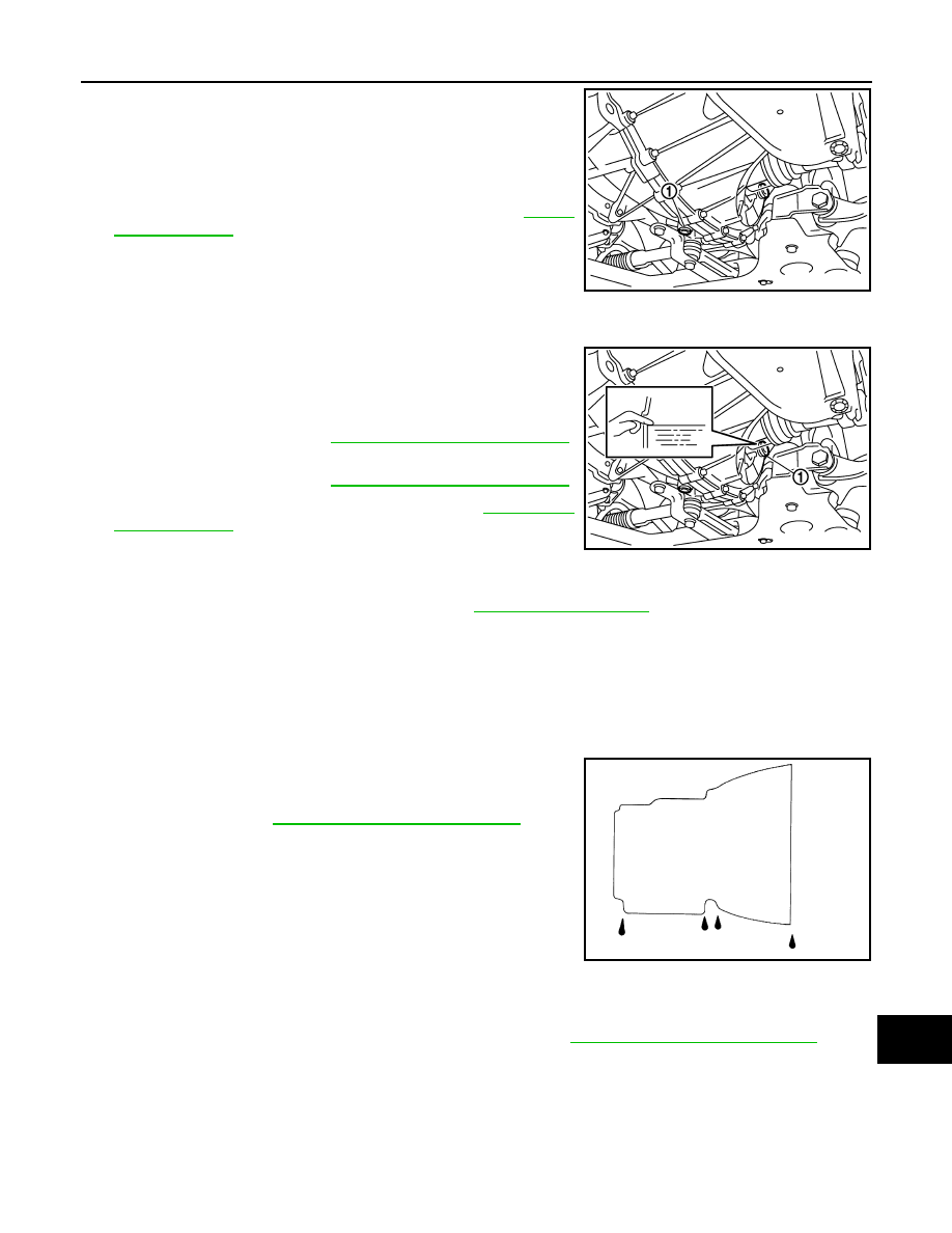
2. Stop engine. Remove drain plug (1) and gasket, using a suitable

tool and then drain gear oil.

3. Set a gasket on drain plug and install it to clutch housing, using

a suitable tool.

CAUTION:

Do not reuse gasket.

4. Tighten drain plug to the specified torque. Refer to 

TM-30,

"Exploded View"

.

CAUTION:

Do not overtighten the filler plug as this could cause the

transaxle case to crack.

M/T OIL : Refilling

INFOID:0000000009756198

1. Remove filler plug (1) and gasket from transaxle case. 
2. Fill with new gear oil until oil level reaches the specified limit at

filler plug mounting hole as shown.

3. After refilling gear oil, check the oil level. Refer to 

MA-22, "M/T

OIL : Inspection"

.

4. Set a gasket on filler plug and then install it to transaxle case.

CAUTION:

Do not reuse gasket.

5. Tighten filler plug to the specified torque. Refer to 

TM-30, "Exploded View"

.

CAUTION:

Do not overtighten the filler plug as this could cause the transaxle case to crack.

CVT FLUID
CVT FLUID : Inspection

INFOID:0000000009756199

FLUID LEAKAGE

• Check transaxle surrounding area (oil seal and plug etc.) for fluid

leakage.

• If anything is found, repair or replace damaged parts and adjust

CVT fluid level. Refer to 

MA-25, "CVT FLUID : Adjustment"

.

CVT FLUID : Replacement

INFOID:0000000009756200

CAUTION:

• Use only recommended CVT fluid. Using transmission fluid other than recommended CVT fluid will

damage the CVT, which is not covered by the warranty.

• Always use shop paper. Do not use shop cloth.

• Replace a drain plug gasket with new ones at the final stage of the operation when installing.

• Use caution when looking into the drain hole as there is a risk of dripping fluid entering the eye.

• After replacement, always perform CVT fluid leakage check.

SCIA7622E

Oil grade and 
viscosity

: Refer to 

MA-11, "Fluids and Lubricants"

.

Oil capacity

: Refer to 

MA-11, "Fluids and Lubricants"

.

SCIA7623E

SMA146B

Recommended CVT fluid and fluid capacity

: Refer to 

TM-288, "General Specification"

.

MA-24

< PERIODIC MAINTENANCE >

CHASSIS AND BODY MAINTENANCE

1. Select “Data Monitor” in “TRANSMISSION” using CONSULT. 
2. Select “FLUID TEMP” and confirm that the CVT fluid temperature is 40

°C (104°F) or less. 

3. Check that the selector lever is in the “P” position, then completely engage the parking brake.
4. Lift up the vehicle.
5. Remove the drain plug and overflow tube and drain the CVT fluid from the oil pan. Refer to 

TM-266,

"Exploded View"

.

6. Install the charging pipe set (KV311039S0) (A) into the drain

hole.

CAUTION:

Tighten the charging pipe by hand.

7. Install the ATF changer hose (B) to the charging pipe.

CAUTION:

Press the ATF changer hose all the way onto the charging

pipe until it stops.

8. Fill approximately 3 liter (2-5/8 lmp qt) of the CVT fluid. 
9. Remove the ATF changer hose and charging pipe, then install

the drain plug.

NOTE:

Perform this work quickly because CVT fluid leaks. 

10. Lift down the vehicle.
11. Start the engine.
12. While depressing the brake pedal, shift the selector lever to the entire position from “P” to “L”, and shift it

to the “P” position.

NOTE:

Hold the lever at each position for 5 seconds.

13. Check that the CONSULT “Data monitor” in “FLUID TEMP” is 35

°C (95°F) to 45°C (113°F).

14. Stop the engine.
15. Lift up the vehicle.
16. Remove the drain plug, and then drain CVT fluid from oil pan.
17. Repeat steps 6 to 16 (one time).
18. Install the overflow tube. Refer to 

TM-266, "Exploded View"

.

CAUTION:

Be sure to tighten to the specified torque. If it is not tightened to the specified torque, the tube may

be damaged.

19. Install the charging pipe set (KV311039S0) (A) into the drain

hole.

CAUTION:

Tighten the charging pipe by hand.

20. Install the ATF changer hose (B) to the charging pipe.

CAUTION:

Press the ATF changer hose all the way onto the charging

pipe until it stops.

21. Fill approximately 3 liter (2-5/8 lmp qt) of the CVT fluid. 
22. Remove the ATF changer hose and charging pipe, then install

the drain plug.

NOTE:

Perform this work quickly because CVT fluid leaks. 

23. Lift down the vehicle.
24. Start the engine.
25. While depressing the brake pedal, shift the selector lever to the entire position from “P” to “L”, and shift it

to the “P” position.

NOTE:

Hold the lever at each position for 5 seconds.

26. Check that the CONSULT “Data monitor” in “FLUID TEMP” is 35

°C (95°F) to 45°C (113°F).

JSDIA1876ZZ

JSDIA1876ZZ

CHASSIS AND BODY MAINTENANCE

MA-25

< PERIODIC MAINTENANCE >

C

D

E

F

G

H

I

J

K

L

M

B

MA

N

O

A

27. Lift up the vehicle.
28. Remove the drain plug and confirm that the CVT fluid is drained from the overflow tube. 

CAUTION:

Perform this work with the vehicle idling.

NOTE:

If the CVT fluid is not drained, refer to “Adjustment” and refill with the CVT fluid. 

29. When the flow of CVT fluid slows to a drip, tighten the drain plug to the specified torque. Refer to 

TM-266,

"Exploded View"

.

CAUTION:

Do not reuse drain plug gasket.

30. Lift down the vehicle.
31. Select “Work Support” in “TRANSMISSION” using CONSULT. 
32. Select “CONFORM CVTF DETERIORTN”.
33. Touch “Erase”.
34. Stop the engine.

CVT FLUID : Adjustment

INFOID:0000000009756201

CAUTION:

• Use only recommended CVT fluid. Using transmission fluid other than recommended CVT fluid will

damage the CVT, which is not covered by the warranty.

• During adjustment of the CVT fluid level, check CONSULT so that the oil temperature may be main-

tained from 35 to 45

°C (95 to 113°F).

• Use caution when looking into the drain hole as there is a risk of dripping fluid entering the eye.
1. Check that the selector lever is in the “P” position, then completely engage the parking brake.
2. Start the engine.
3. Adjust the CVT fluid temperature to be approximately 40

°C (104°F). 

NOTE:

The CVT fluid is largely affected by temperature. Therefore be sure to use CONSULT and check the

“FLUID TEMP” under “TRANSMISSION” in “Data Monitor” while adjusting.

4. While depressing the brake pedal, shift the selector lever to the entire position from “P” to “L”, and shift it

to the “P” position.

NOTE:

Hold the lever at each position for 5 seconds.

5. Lift up the vehicle.
6. Check that there is no CVT fluid leakage.
7. Remove the drain plug. Refer to 

TM-266, "Exploded View"

.

8. Install the charging pipe set (KV311039S0) (A) into the drain

plug hole.

CAUTION:

Tighten the charging pipe by hand.

9. Install the ATF changer hose (B) to the charging pipe.

CAUTION:

Press the ATF changer hose all the way onto the charging

pipe until it stops.

10. Fill approximately 0.5 liter (1/2 lmp qt) of the CVT fluid. 
11. Remove the ATF changer hose from the charging pipe, and

check that the CVT fluid drains out from the charging pipe. If it

does not drain out, perform charging again.

CAUTION:

Perform this work with the vehicle idling.

12. When the flow of CVT fluid slows to a drip, remove the charging pipe from the oil pan. 
13. Tighten the drain plug to the specified torque. Refer to 

TM-266, "Exploded View"

.

Recommended CVT fluid and fluid capacity

: Refer to 

TM-288, "General Specification"

.

JSDIA1876ZZ

MA-26

< PERIODIC MAINTENANCE >

CHASSIS AND BODY MAINTENANCE

CAUTION:

Do not reuse drain plug gasket.

14. Lift down the vehicle.
15. Stop the engine.

WHEELS
WHEELS : Inspection

INFOID:0000000009756202

ALUMINUM WHEEL

1. Check tires for wear and improper inflation.
2. Check wheels for deformation, cracks and other damage. If deformed, remove wheel and check wheel

runout.

a. Remove tire from aluminum wheel and mount wheel on a balancer machine.
b. Set dial indicator as shown.
c.

Check runout, if runout value exceeds the limit, replace alumi-

num wheel.

STEEL WHEEL

1. Check tires for wear and improper inflation.
2. Check wheels for deformation, cracks and other damage. If deformed, remove wheel and check wheel

runout.

a. Remove tire from steel wheel and mount wheel on a balancer machine.
b. Set two dial indicators as shown.
c.

Set each dial indicator to "0".

d. Rotate wheel and check dial indicators at several points around

the circumference of the wheel.

e. Calculate runout at each point as shown below.

f.

Select maximum positive runout value and the maximum nega-

tive value.

Add the two values to determine total runout.

In case a positive or negative value is not available, use the

maximum value (negative or positive) for total runout.

If the total runout value exceeds the limit, replace steel wheel.

WHEELS : Adjustment

INFOID:0000000009756203

BALANCING WHEELS (ADHESIVE WEIGHT TYPE)

Limit
Lateral Deflection (A)

Refer to 

WT-54, "Road Wheel"

.

Radial Deflection (B)

Refer to 

WT-54, "Road Wheel"

.

SEIA0737E

Lateral deflection (A) = (W+X)/2
Radial deflection (B) = (Y+Z)/2

Limit
Lateral Deflection (A)

Refer to 

WT-54, "Road Wheel"

.

Radial Deflection (B)

Refer to 

WT-54, "Road Wheel"

.

AWEIA0186ZZ


Content   ..  628  629  630  631   ..