Nissan Sentra. Manual - part 160
SYSTEM
BRC-27
< SYSTEM DESCRIPTION >
[VDC/TCS/ABS]
C
D
E
G
H
I
J
K
L
M
A
B
BRC
N
O
P
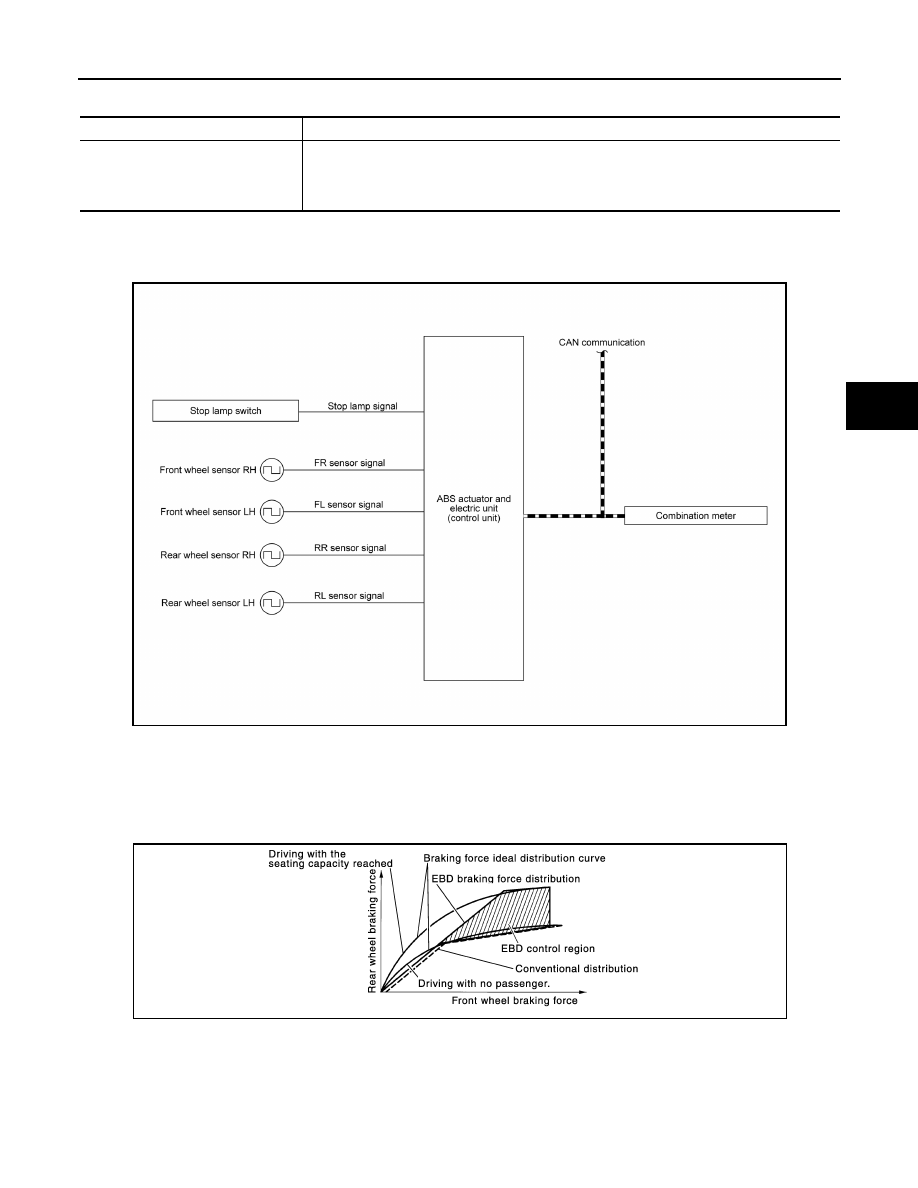
Major signal transmission between each unit via communication lines is shown in the following table.
VDC/TCS/ABS : EBD Function
INFOID:0000000009757821
SYSTEM DIAGRAM
• By preventing rear wheel slip increase through rear wheel brake force (brake fluid pressure) control that is
electronically controlled when slight skip on front and rear wheels are detected during braking, stability dur-
ing braking is improved.
• EBD function is expanded and developed from conventional ABS function and corrects rear wheel brake
force to appropriate level by electronic control according to load weight (number of passengers).
Component
Signal description
Combination meter
Receives the following signals from ABS actuator and electric unit (control unit) via CAN com-
munication.
• VDC warning lamp signal
• ABS warning lamp signal
AWFIA0808GB
JPFIC0142GB