Nissan Sentra. Manual - part 158


  Index      Nissan     Nissan Sentra (2014 year) - Service and Repair Manual


Search            


Content   ..  156  157  158  159   ..


Nissan Sentra. Manual - part 158


SYSTEM

BRC-19

< SYSTEM DESCRIPTION >

[VDC/TCS/ABS]

C

D

E

G

H

I

J

K

L

M

A

B

BRC

N

O

P

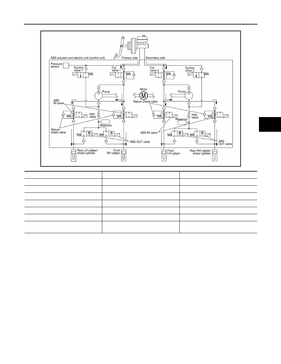
ABS Function Operating (Pressure Increases)

Front RH brake caliper

• Brake fluid is supplied to the front RH brake caliper from the master cylinder through the cut valve 1 and the

ABS IN valve. Since the suction valve 1 and the ABS OUT valve is closed, the fluid does not flow into the

reservoir. The amount of brake fluid supplied to the front RH brake caliper from the master cylinder is con-

trolled according to time that the ABS IN valve is not energized (time that the ABS IN valve is open).

Front LH brake caliper

• Brake fluid is supplied to the front LH brake caliper from the master cylinder through the cut valve 2 and the

ABS IN valve. Since the suction valve 2 and the ABS OUT valve is closed, the fluid does not flow into the

reservoir. The amount of brake fluid supplied to the front LH brake caliper from the master cylinder is con-

trolled according to time that the ABS IN valve is not energized (time that the ABS IN valve is open).

Rear RH brake caliper/wheel cylinder

• Brake fluid is supplied to the rear RH brake caliper/wheel cylinder from the master cylinder through the cut

valve 2 and the ABS IN valve. Since the suction valve 2 and the ABS OUT valve is closed, the fluid does not

flow into the reservoir. The amount of brake fluid supplied to the rear RH brake caliper/wheel cylinder from

the master cylinder is controlled according to time that the ABS IN valve is not energized (time that the ABS

IN valve is open).

Rear LH brake caliper/wheel cylinder

ALFIA0335GB

Name

Not activated

During pressure increases

Cut valve 1

Power supply is not supplied (open)

Power supply is not supplied (open)

Cut valve 2

Power supply is not supplied (open)

Power supply is not supplied (open)

Suction valve 1

Power supply is not supplied (close)

Power supply is not supplied (close)

Suction valve 2

Power supply is not supplied (close)

Power supply is not supplied (close)

ABS IN valve

Power supply is not supplied (open)

Power supply is not supplied (open)

ABS OUT valve

Power supply is not supplied (close)

Power supply is not supplied (close)

Each brake caliper and each wheel cylinder 
(fluid pressure)

Pressure increases

BRC-20

< SYSTEM DESCRIPTION >

[VDC/TCS/ABS]

SYSTEM

• Brake fluid is supplied to the rear LH brake caliper/wheel cylinder from the master cylinder through the cut

valve 1 and the ABS IN valve. Since the suction valve 1 and the ABS OUT valve is closed, the fluid does not

flow into the reservoir. The amount of brake fluid supplied to the rear LH brake caliper/wheel cylinder from

the master cylinder is controlled according to time that the ABS IN valve is not energized (time that the ABS

IN valve is open).

Brake Release

Front RH brake caliper

• Brake fluid is supplied to the front RH brake caliper through the return check valve of the ABS IN valve and

the cut valve 1, and returns to the master cylinder.

Front LH brake caliper

• Brake fluid is supplied to the front LH brake caliper through the return check valve of the ABS IN valve and

the cut valve 2, and returns to the master cylinder.

Rear RH brake caliper/wheel cylinder

• Brake fluid is supplied to the rear RH brake caliper/wheel cylinder through the return check valve of the ABS

IN valve and the cut valve 2, and returns to the master cylinder.

Rear LH brake caliper/wheel cylinder

• Brake fluid is supplied to the rear LH brake caliper/wheel cylinder through the return check valve of the ABS

IN valve and the cut valve 1, and returns to the master cylinder.

ALFIA0338GB

Name

Not activated

During brake release

Cut valve 1

Power supply is not supplied (open)

Power supply is not supplied (open)

Cut valve 2

Power supply is not supplied (open)

Power supply is not supplied (open)

Suction valve 1

Power supply is not supplied (close)

Power supply is not supplied (close)

Suction valve 2

Power supply is not supplied (close)

Power supply is not supplied (close)

ABS IN valve

Power supply is not supplied (open)

Power supply is not supplied (open)

ABS OUT valve

Power supply is not supplied (close)

Power supply is not supplied (close)

Each brake caliper and each wheel cylinder 
(fluid pressure)

Pressure decreases

SYSTEM

BRC-21

< SYSTEM DESCRIPTION >

[VDC/TCS/ABS]

C

D

E

G

H

I

J

K

L

M

A

B

BRC

N

O

P

Component Parts and Function

CONDITIONS FOR INDICATOR LAMP ILLUMINATION

• Turns ON when VDC and TCS functions are switched to non-operational status (OFF) by VDC OFF switch.

• Turns ON when ignition switch turns ON and turns OFF when the system is normal, for bulb check purposes.

CONDITIONS FOR WARNING LAMP ILLUMINATION

Turns ON when ignition switch turns ON and turns OFF when the system is normal, for bulb check purposes.

Component

Function

Pump

Returns the brake fluid reserved in reservoir to master cylinder by reducing pressure.

Motor

Activates the pump according to signals from ABS actuator and electric unit (control unit).

Cut valve 1
Cut valve 2

Shuts off the ordinary brake line from master cylinder.

Suction valve 1
Suction valve 2

Supplies the brake fluid from master cylinder to the pump.

ABS IN valve

Switches the fluid pressure line to increase or hold according to signals from control unit.

ABS OUT valve

Switches the fluid pressure line to increase, hold or decrease according to signals from control unit.

Return check valve

Returns the brake fluid from brake caliper and wheel cylinder to master cylinder by bypassing orifice 
of each valve when brake is released.

Reservoir

Temporarily reserves the brake fluid drained from brake caliper, so that pressure efficiently decreas-
es when decreasing pressure of brake caliper and wheel cylinder.

Pressure sensor

Detects the brake fluid pressure and transmits signal to ABS actuator and electric unit (control unit).

Condition (status)

VDC OFF indicator lamp

SLIP indicator lamp

Ignition switch OFF

OFF

OFF

For approx. 1 second after the ignition switch 
is turned ON

ON

ON

Approx. 1 second after ignition switch is 
turned ON (when the system is in normal op-
eration)

OFF

OFF

When VDC OFF switch is ON (VDC function 
and TCS function are OFF)

ON

OFF

VDC function is malfunctioning

OFF

ON

TCS function is malfunctioning

OFF

ON

Condition (status)

ABS warning lamp

Brake warning lamp

Ignition switch OFF

OFF

OFF

For approx. 1 second after the ignition switch 
is turned ON

ON

ON

Approx. 1 second after ignition switch is 
turned ON (when the system is in normal op-
eration)

OFF

OFF

After engine starts

OFF

OFF

When parking brake operates (parking brake 
switch ON)

OFF

ON

When brake fluid is less than the specified 
level (brake fluid level switch ON)

OFF

ON

VDC function is malfunctioning

OFF

OFF

TCS function is malfunctioning

OFF

OFF

ABS function is malfunctioning

ON

OFF

EBD function is malfunctioning

ON

ON

BRC-22

< SYSTEM DESCRIPTION >

[VDC/TCS/ABS]

SYSTEM

VDC/TCS/ABS : VDC Function

INFOID:0000000009757818

SYSTEM DIAGRAM

SYSTEM DESCRIPTION

• Side slip or tail slip may occur while driving on a slippery road or intending an urgent evasive driving maneu-

ver. VDC function detects side slip status using each sensor when side slip or tail slip is about to occur and

improves vehicle stability by brake control and engine output control during driving.

• In addition to ABS function, EBD function and TCS function, target side slip amount is calculated according

to steering operation amount from steering angle sensor. By comparing this information with vehicle side slip

amount that is calculated from information from yaw rate/side G sensor and wheel sensor, vehicle driving

conditions (conditions of understeer or oversteer) are judged and vehicle stability is improved by brake force

control on all 4 wheels and engine output control.

• VDC function can be switched to non-operational status (OFF) by operating VDC OFF switch. In this case,

VDC OFF indicator lamp turns ON.

• Control unit portion automatically improves driving stability by performing brake force control as well as

engine output control, by transmitting drive signal to actuator portion according to difference between target

side slip amount and vehicle side slip amount 

Brake limited slip differential (BLSD) function 
is malfunctioning

OFF

OFF

VDC function is operating

OFF

OFF

TCS function is operating

OFF

OFF

Condition (status)

ABS warning lamp

Brake warning lamp

AWFIA0807GB

JSFIA0672GB


Content   ..  156  157  158  159   ..