Nissan Sentra. Manual - part 159


  Index      Nissan     Nissan Sentra (2014 year) - Service and Repair Manual


Search            


Content   ..  157  158  159  160   ..


Nissan Sentra. Manual - part 159


SYSTEM

BRC-23

< SYSTEM DESCRIPTION >

[VDC/TCS/ABS]

C

D

E

G

H

I

J

K

L

M

A

B

BRC

N

O

P

• Brake force control function at braking hard detects driver

′s brake operations with the pressure sensor,

judges a brake booster

′s maximum brake power function by using information from the vacuum sensor, and

enhances more powerful braking force by controlling brakes of four wheels.

• VDC warning lamp blinks while VDC function is in operation and indicates to the driver that the function is in

operation.

• CONSULT can be used to diagnose the system.

• Fail-safe function is adopted. When a malfunction occurs in VDC function, the control is suspended for VDC

function and TCS function. However, ABS function and EBD function operate normally. Refer to 

BRC-39,

"Fail-safe"

.

INPUT SIGNAL AND OUTPUT SIGNAL

Major signal transmission between each unit via communication lines is shown in the following table.

OPERATION CHARACTERISTICS

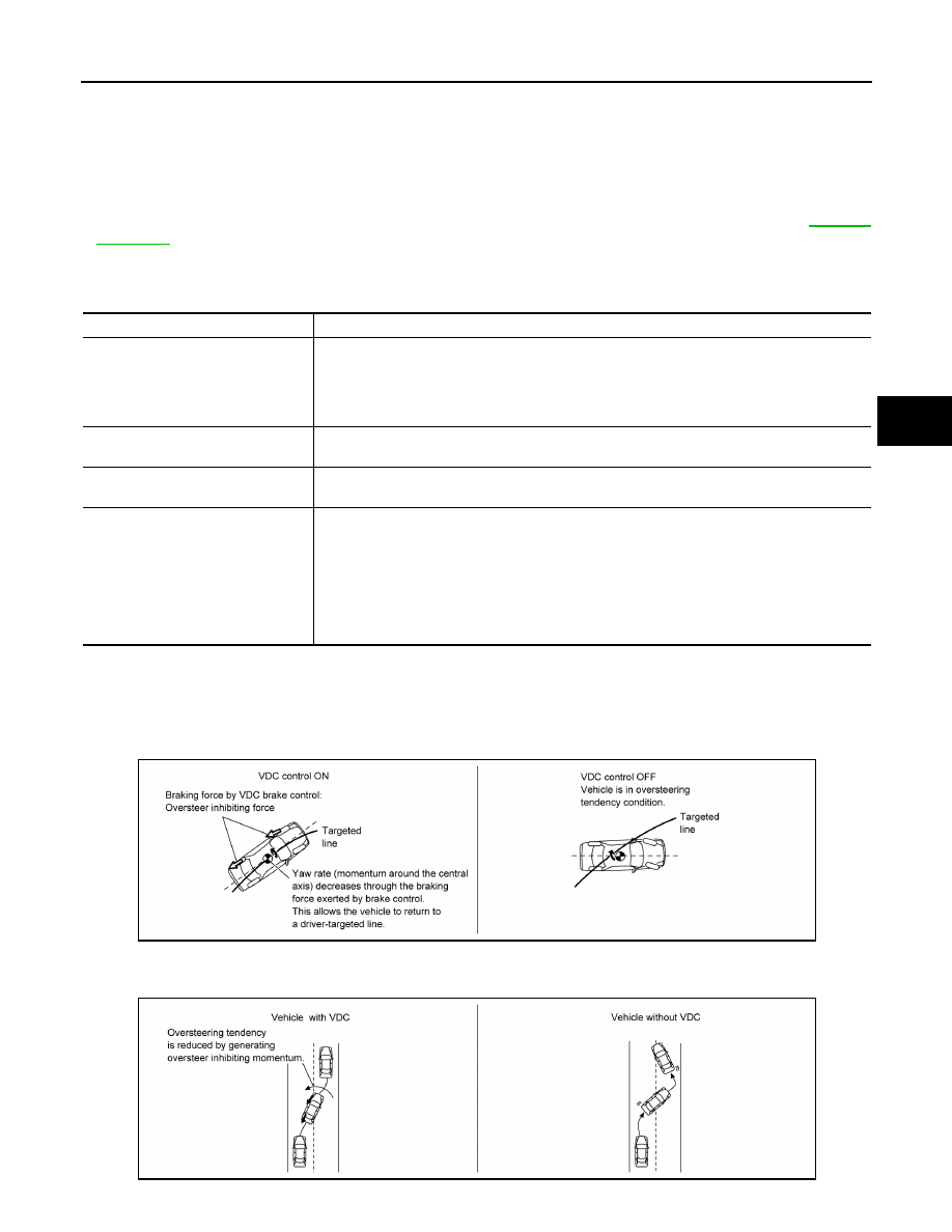
VDC Function That Prevents Oversteer Tendency

• During cornering, brake force (brake fluid pressure) is applied on front wheel and rear wheel on the outer

side of turn. Momentum is generated directing the vehicle toward the outer side of the turn. Oversteer is pre-

vented.

• Changing driving lane on a slippery road, when there may be a tendency to oversteer, engine output is con-

trolled as well as brake force (brake fluid pressure) of 4 wheels. Oversteer tendency decreases.

Component

Signal description

ECM

Transmits the following signals to ABS actuator and electric unit (control unit) via CAN commu-
nication.
• Acceleration pedal position signal
• Engine speed signal
• Target throttle position signal

TCM

Transmits the current gear position signal to ABS actuator and electric unit (control unit) via 
CAN communication.

Steering angle sensor

Transmits the steering angle sensor signal to ABS actuator and electric unit (control unit) via 
CAN communication.

Combination meter

Transmits the following signals to ABS actuator and electric unit (control unit) via CAN commu-
nication.
• Brake fluid level switch signal
• parking brake switch signal
Receives the following signals from ABS actuator and electric unit (control unit) via CAN com-
munication.
• VDC OFF indicator lamp signal
• SLIP indicator lamp signal

ALFIA0339GB

ALFIA0340GB

BRC-24

< SYSTEM DESCRIPTION >

[VDC/TCS/ABS]

SYSTEM

VDC Function That Prevents Understeer Tendency

• During cornering, brake force (brake fluid pressure) is applied on front wheel and rear wheel on the inner

side of turn. Momentum is generated directing the vehicle toward the inner side of the turn. Understeer is

prevented.

• Applying brakes during cornering on a slippery road, when there may be a tendency to understeer, engine

output is controlled as well as brake force (brake fluid pressure) of 4 wheels. Understeer tendency

decreases.

VDC/TCS/ABS : TCS Function

INFOID:0000000009757819

SYSTEM DIAGRAM

SYSTEM DESCRIPTION

JPFIC0137GB

ALFIA0341GB

AWFIA0807GB

SYSTEM

BRC-25

< SYSTEM DESCRIPTION >

[VDC/TCS/ABS]

C

D

E

G

H

I

J

K

L

M

A

B

BRC

N

O

P

• Wheel spin status of drive wheel is detected by wheel sensor of 4

wheels. Engine output and transmission shift status is controlled

so that slip rate of drive wheels is in appropriate level. When wheel

spin occurs on drive wheel, ABS actuator and electric unit (control

unit) perform brake force control of LH and RH drive wheels (apply

brake force by increasing brake fluid pressure of drive wheel) and

decrease engine torque by engine torque control. Wheel spin

amount decreases. Engine torque is controlled to appropriate

level.

• TCS function can be switched to non-operational status (OFF) by

operating VDC OFF switch. In this case, VDC OFF indicator lamp

turns ON.

• SLIP indicator lamp blinks while TCS function is in operation and

indicates to the driver that the function is in operation.

• CONSULT can be used to diagnose the system.

• Fail-safe function is adopted. When a malfunction occurs in TCS

function, the control is suspended for VDC function and TCS func-

tion. However, ABS function and EBD function operate normally.

Refer to 

BRC-39, "Fail-safe"

.

INPUT SIGNAL AND OUTPUT SIGNAL

Major signal transmission between each unit via communication lines is shown in the following table.

JPFIC0139GB

Component

Signal description

ECM

Transmits the following signals to ABS actuator and electric unit (control unit) via CAN commu-
nication.
• Accelerator pedal position signal
• Engine speed signal
• Target throttle position signal

TCM

Transmits the current gear position signal to ABS actuator and electric unit (control unit) via 
CAN communication.

Steering angle sensor

Transmits the steering angle sensor signal to ABS actuator and electric unit (control unit) via 
CAN communication.

Combination meter

Transmits the following signals to ABS actuator and electric unit (control unit) via CAN commu-
nication.
• Brake fluid level switch signal
• Parking brake switch signal
Receives the following signals from ABS actuator and electric unit (control unit) via CAN com-
munication.
• VDC OFF indicator lamp signal
• SLIP indicator lamp signal

BRC-26

< SYSTEM DESCRIPTION >

[VDC/TCS/ABS]

SYSTEM

VDC/TCS/ABS : ABS Function

INFOID:0000000009757820

SYSTEM DIAGRAM

• By preventing wheel lock through brake force (brake fluid pressure) control that is electronically controlled by

detecting wheel speed during braking, stability during emergency braking is improved so that obstacles can

be easily bypassed by steering operation.

• During braking, control units calculate wheel speeds, and transmit pressure increase, hold or decrease sig-

nals to actuator portion according to wheel slip status.

• The following effects are obtained by preventing wheel lock during

braking.

- Vehicle tail slip is prevented during braking when driving straight.

- Understeer and oversteer tendencies are moderated during brak-

ing while cornering.

- Obstacles may be easily bypassed by steering operation during

braking.

• CONSULT can be used to diagnose the system.

• Fail-safe function is adopted. When a malfunction occurs in ABS

function, the control is suspended for VDC function, TCS function

and ABS function. However, EBD function operates normally.

Refer to 

BRC-28, "VDC/TCS/ABS : Fail-safe"

.

INPUT SIGNAL AND OUTPUT SIGNAL

AWFIA0808GB

JPFIC0140GB


Content   ..  157  158  159  160   ..