Nissan Sentra. Manual - part 18


  Index      Nissan     Nissan Sentra (2014 year) - Service and Repair Manual


Search            


Content   ..  16  17  18  19   ..


Nissan Sentra. Manual - part 18


AV-64

< REMOVAL AND INSTALLATION >

[BASE AUDIO]

ANTENNA FEEDER

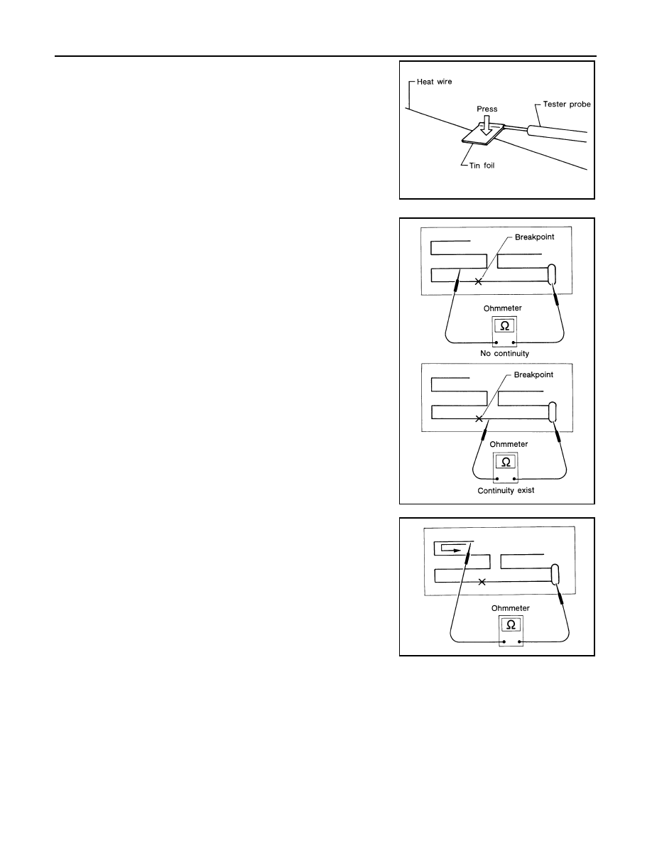
• When measuring continuity, wrap tin foil around the top of

probe. Then, press the foil against the wire with your finger.

2. If an element is broken, no continuity will exist.

3. To locate a break, move probe along element. Tester indication

will change abruptly when probe passes the broken point.

REPAIR EQUIPMENT

• Conductive silver composition (DuPont No. 4817 or equivalent)

• Ruler 30 cm (11.8 in) long

• Drawing pen

• Heat gun

• Alcohol

• Cloth

REPAIRING PROCEDURE

SEL122R

SEL252I

SEL253I

AV

ANTENNA FEEDER

AV-65

< REMOVAL AND INSTALLATION >

[BASE AUDIO]

C

D

E

F

G

H

I

J

K

L

M

B

A

O

P

1. Wipe broken heat wire and its surrounding area clean with a

cloth dampened in alcohol.

2. Apply a small amount of conductive silver composition to tip of

drawing pen.

Shake silver composition container before use.

3. Place ruler on glass along broken line. Deposit conductive silver

composition on break with drawing pen. Slightly overlap existing

heat wire on both sides [preferably 5 mm (0.20 in)] of the break.

4. After repair has been completed, check repaired wire for conti-

nuity. This check should be conducted 10 minutes after silver

composition is deposited.

Do not touch repaired area while test is being conducted.

5. Apply a constant stream of hot air directly to the repaired area

for approximately 20 minutes with a heat gun. A minimum dis-

tance of 3 cm (1.2 in) should be kept between repaired area and

hot air outlet.

If a heat gun is not available, let the repaired area dry for 24

hours.

PIIA0215E

SEL012D

SEL013D

AV-66

< REMOVAL AND INSTALLATION >

[BASE AUDIO]

ANTENNA AMP.

ANTENNA AMP.

Removal and Installation

INFOID:0000000009758830

REMOVAL

1. Remove the rear pillar finisher (RH). Refer to 

INT-29, "REAR PILLAR FINISHER : Removal and Installa-

tion"

.

2. Disconnect the antenna amp. harness connector (A) from the

rear window glass. 

3. Disconnect the harness connector (C) from the antenna amp.

(1).

4. Remove the antenna amp. screw (B) and the antenna amp. (1).

INSTALLATION

Installation is in the reverse order of removal.

ALNIA1410ZZ

AV

WINDOW ANTENNA

AV-67

< REMOVAL AND INSTALLATION >

[BASE AUDIO]

C

D

E

F

G

H

I

J

K

L

M

B

A

O

P

WINDOW ANTENNA

Removal and Installation

INFOID:0000000010296640

The window antenna is serviced as an assembly with the filament. Refer to 

DEF-47, "Inspection and Repair"

.


Content   ..  16  17  18  19   ..