Nissan Leaf. Manual - part 988
PCS
SYSTEM
PCS-35
< SYSTEM DESCRIPTION >
[POWER DISTRIBUTION SYSTEM]
C
D
E
F
G
H
I
J
K
L
B
A
O
P
N
SYSTEM
POWER DISTRIBUTION SYSTEM
POWER DISTRIBUTION SYSTEM : System Description
INFOID:0000000010120310
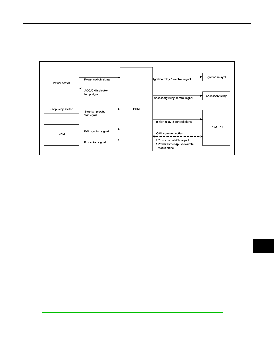
SYSTEM DIAGRAM
SYSTEM DESCRIPTION
• PDS (POWER DISTRIBUTION SYSTEM) is the system that BCM controls with the operation of power
switch and performs the power distribution to each power circuit. This system is used instead of the mechan-
ical power supply changing mechanism with the operation of the conventional key cylinder.
• Power switch (push switch) can be operated when Intelligent Key is in the following condition.
- Intelligent Key is in the detection area of the interior antenna.
- Intelligent Key backside is contacted to power switch.
• Power switch (push switch) operation is input to BCM as a signal. BCM changes the power switch position
according to the status and operates the following relays to supply power to each power circuit.
- Ignition relay-1
- Ignition relay-2
- ACC relay
• The power switch position can be confirmed with the lighting of ACC/ON indicator in power switch (push
switch).
BATTERY SAVER SYSTEM
When all the following conditions are met for 30 minutes, the battery saver system will cut off the power supply
to prevent 12V battery discharge.
• Power switch is in the ACC position
• All doors are closed
• Shift position is in the P position
Reset Condition of Battery Saver System
If any of the following conditions are met the battery saver system is released.
• Opening any door
• Operating with request switch on door lock
• Operating with Intelligent Key on door lock
• Press power switch (push switch), and power switch will change to ACC position from OFF position.
READY SET CONDITION TABLE BY POWER SWITCH OPERATION
SEC-12, "INTELLIGENT KEY SYSTEM/READY SET FUNCTION : System Description"
.
Fail-safe
INFOID:0000000010563595
FAIL-SAFE CONTROL BY DTC
BCM performs fail-safe control when any DTC are detected.
AWMIA1408GB