Nissan Leaf. Manual - part 941


  Index      Nissan     Nissan Leaf (2011-2014 year) - Service and Repair Manual


Search            


Content   ..  939  940  941  942   ..


Nissan Leaf. Manual - part 941


MA-22

< PERIODIC MAINTENANCE >

EV SYSTEM MAINTENANCE

• Malfunction in opening/closing the charge port caps and looseness when closed and locked.
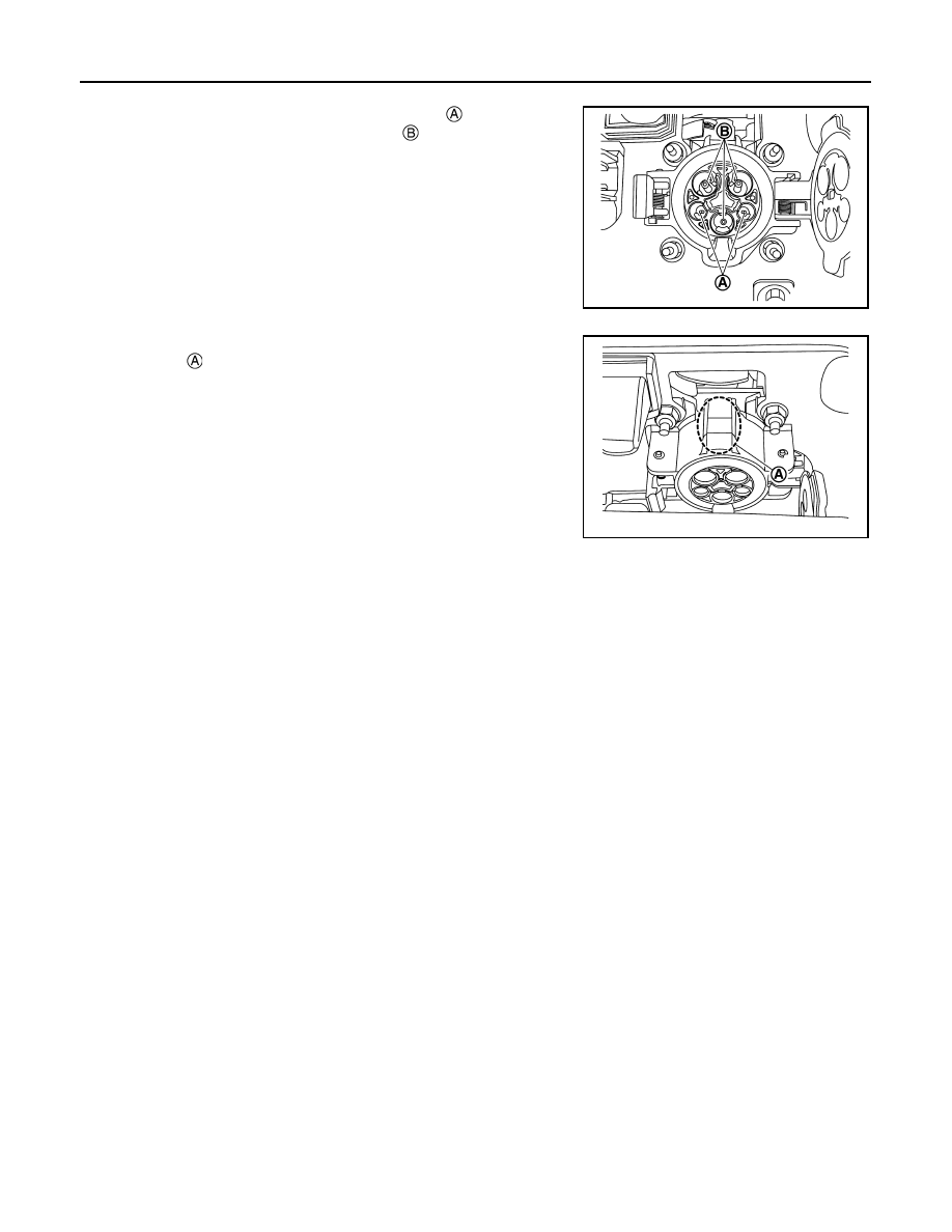
• Check that the normal charge port terminals   are not bent.
• Check that the contact prevention cap   is not missing.

NOTE:

If it is missing, it is extremely difficult to engage the charge

connector.

• Check that there is no snow or ice on the normal charge port

top side  .

NOTE:

If snow or ice reaches the charge connector lock, charging

does not start.

Handling of charge port

Cleaning of charge port

If the charge port becomes dirty, clean the port with an air blow gun.

Handling of damaged cap

Perform the following procedure if the cap becomes damaged:

•  Replace charge port cap if the charge port cap becomes damaged

•  Replace charge port if the packing of quick charge port becomes cracked.

•  Replace charge port if the terminal of quick charge port or normal charge port becomes damaged.

Cleaning of the inside of rubber cap

If air does not exit through the rubber cap hole, remove the rubber cap from the port and clean the inside so

that air exits through the rubber cap hole.

JPCIA0369ZZ

JPCIA0370ZZ

CHASSIS MAINTENANCE

MA-23

< PERIODIC MAINTENANCE >

C

D

E

F

G

H

I

J

K

L

M

B

MA

N

O

A

CHASSIS MAINTENANCE

REDUCTION GEAR OIL
REDUCTION GEAR OIL : Inspection

INFOID:0000000010121530

OIL LEAKAGE 

Check reduction gear surrounding area (oil seal, drain plug, and filler plug etc.) for oil leakage.

OIL LEVEL

• Remove filler plug   and gasket. Then check that oil is filled up

from mounting hole for the filler plug.

CAUTION:

Turn the power switch OFF while checking oil level.

• Set a gasket on filler plug and install it on reduction gear and

tighten to the specified torque. Refer to 

TM-21, "Exploded View"

.

CAUTION:

• Never reuse gasket.

• If foreign matter, such as gear abrasion powder, is on the

magnet of the filler plug, wipe it free of adherents before

installation.

REDUCTION GEAR OIL : Draining and Refilling

INFOID:0000000010121531

DRAINING

1. Turn the power switch OFF.
2. Remove filler plug.
3. Remove drain plug   and drain gear oil.
4. Set a gasket on drain plug and install it to reduction gear and

tighten to the specified torque. Refer to 

TM-21, "Exploded View"

.

CAUTION:

• Never reuse gasket.

• If foreign matter, such as gear abrasion powder, is on the

magnet of the drain plug, wipe it free of adherents before

installation.

REFILLING

1. Remove filler plug  . Fill with new gear oil until oil level reaches

the specified level near filler plug mounting hole.

2. After refilling oil, check oil level. Set a gasket on filler plug, then

install it to reduction gear. Refer to 

TM-21, "Exploded View"

.

CAUTION:

• Never reuse gasket.

• If foreign matter, such as gear abrasion powder, is on the magnet of the filler plug, wipe it free of

adherents before installation.

WHEELS

JSDIA3975ZZ

JSDIA3976ZZ

Oil grade

: Refer to 

MA-16, "FOR USA AND 

CANADA : Fluids and Lubricants"


(United States and Canada) or 

MA-

17, "FOR MEXICO : Fluids and Lubri-
cants"

 (Mexico).

Oil capacity

: Refer to 

TM-27, "General Specifica-

tions"

.

JSDIA3975ZZ

MA-24

< PERIODIC MAINTENANCE >

CHASSIS MAINTENANCE

WHEELS : Inspection

INFOID:0000000010121532

APPEARANCE

Check the road wheel for bend, damage, crack or wear.

WHEELS : Wheel Balance Adjustment

INFOID:0000000010121533

BALANCING WHEELS (ADHESIVE WEIGHT TYPE)

Preparation Before Adjustment

Remove inner and outer balance weights from the road wheel. Using releasing agent, remove double-faced

adhesive tape from the road wheel.

CAUTION:

• Be careful not to scratch the road wheel during removal.

• After removing double-faced adhesive tape, wipe clean all traces of releasing agent from the road

wheel.

Wheel Balance Adjustment

CAUTION:

• DO NOT use center hole cone-type clamping machines to hold the wheel assembly during tire

removal/installation or balancing or damage to the wheel paint, cladding or chrome may result. Use

only rim-type or universal lug-type clamping machines to hold the wheel assembly during servicing.

• If a balancer machine has an adhesive weight mode setting, select the adhesive weight mode setting and

skip Step 2 below. If a balancer machine only has the clip-on (rim flange) weight mode setting, follow Step 2

to calculate the correct size adhesive weight.

1. Set road wheel on balancer machine using the center hole as a guide. Start the balancer machine.
2. For balancer machines that only have a clip-on (rim flange) weight mode setting, follow this step to calcu-

late the correct size adhesive weight to use. When inner and outer imbalance values are shown on the

balancer machine indicator, multiply outer imbalance value by 5/3 (1.67) to determine balance weight that

should be used. Select the outer balance weight with a value closest to the calculated value above and

install in to the designated outer position of or at the designated angle in relation to the road wheel.

a. Indicated imbalance value 

× 5/3 = balance weight to be installed

Calculation example:

23 g (0.81 oz) 

× 5/3 (1.67) = 38.33 g (1.35 oz) ⇒ 40 g (1.41 oz)

balance weight (closer to calculated balance weight value)

NOTE:

Note that balance weight value must be closer to the calculated

balance weight value.

Example:

37.4 

⇒ 35 g (1.23 oz)

37.5 

⇒ 40 g (1.41 oz)

SMA054D

CHASSIS MAINTENANCE

MA-25

< PERIODIC MAINTENANCE >

C

D

E

F

G

H

I

J

K

L

M

B

MA

N

O

A

3. Install balance weight in the position shown.

CAUTION:

• Do not install the inner balance weight before installing

the outer balance weight.

• Before installing the balance weight, be sure to clean the

mating surface of the road wheel.

• When installing balance weight (1) to road wheel, set it into the

grooved area (A) on the inner wall of the road wheel as shown

so that the balance weight center (B) is aligned with the bal-

ancer machine indication position (angle) (C).

CAUTION:

• Always use Genuine NISSAN adhesive balance weights.

• Balance weights are non-reusable; always replace with

new ones.

• Do not install more than three sheets of balance

weights.

4. If calculated balance weight value exceeds 50 g (1.76 oz), install

two balance weight sheets in line with each other as shown.

CAUTION:

Do not install one balance weight sheet on top of another.

5. Start balancer machine again.
6. Install balance weight on inner side of road wheel in the bal-

ancer machine indication position (angle).

CAUTION:

Do not install more than two balance weights.

7. Start balancer machine. Make sure that inner and outer residual

imbalance values are 5 g (0.17 oz) each or below.

8. If either residual imbalance value exceeds 5 g (0.17 oz), repeat installation procedures.

WHEELS : Tire Rotation

INFOID:0000000010121534

• Follow the maintenance schedule for tire rotation service intervals.

Refer to 

MA-7, "FOR USA AND CANADA : Explanation of General

Maintenance"

 (For United States and Canada) or 

MA-8, "FOR

MEXICO : General Maintenance"

 (For Mexico).

• When installing the wheel, tighten wheel nuts to the specified

torque. Refer to 

WT-45, "Exploded View"

.

CAUTION:

• When installing wheels, tighten them diagonally by dividing

the work two to three times in order to prevent the wheels

from developing any distortion.

• Be careful not to tighten wheel nut at torque exceeding the

criteria.

• Use NISSAN genuine wheel nut.

• Perform the ID registration, after tire rotation. Refer to 

WT-21, "Work Procedure"

.

BRAKE FLUID LEVEL AND LEAKS

JPEIC0040ZZ

Wheel balance

Dynamic (At flange)

Static (At flange)

Maximum allowable im-
balance

Refer to 

WT-51, "Road Wheel"

.

PEIA0033E

SMA829C


Content   ..  939  940  941  942   ..