Nissan Leaf. Manual - part 876


  Index      Nissan     Nissan Leaf (2011-2014 year) - Service and Repair Manual


Search            


Content   ..  874  875  876  877   ..


Nissan Leaf. Manual - part 876


BACK DOOR TRIM

INT-49

< REMOVAL AND INSTALLATION >

C

D

E

F

G

H

I

K

L

M

A

B

INT

N

O

P

• Never damage the back door panel.

REMOVAL

1. Fully open back door.
2. Remove back door side finisher. Refer to 

INT-47, "BACK DOOR SIDE FINISHER : Removal and Installa-

tion"

.

3. Remove back door pull handle. Refer to 

INT-48, "BACK DOOR PULL HANDLE : Removal and Installa-

tion"

.

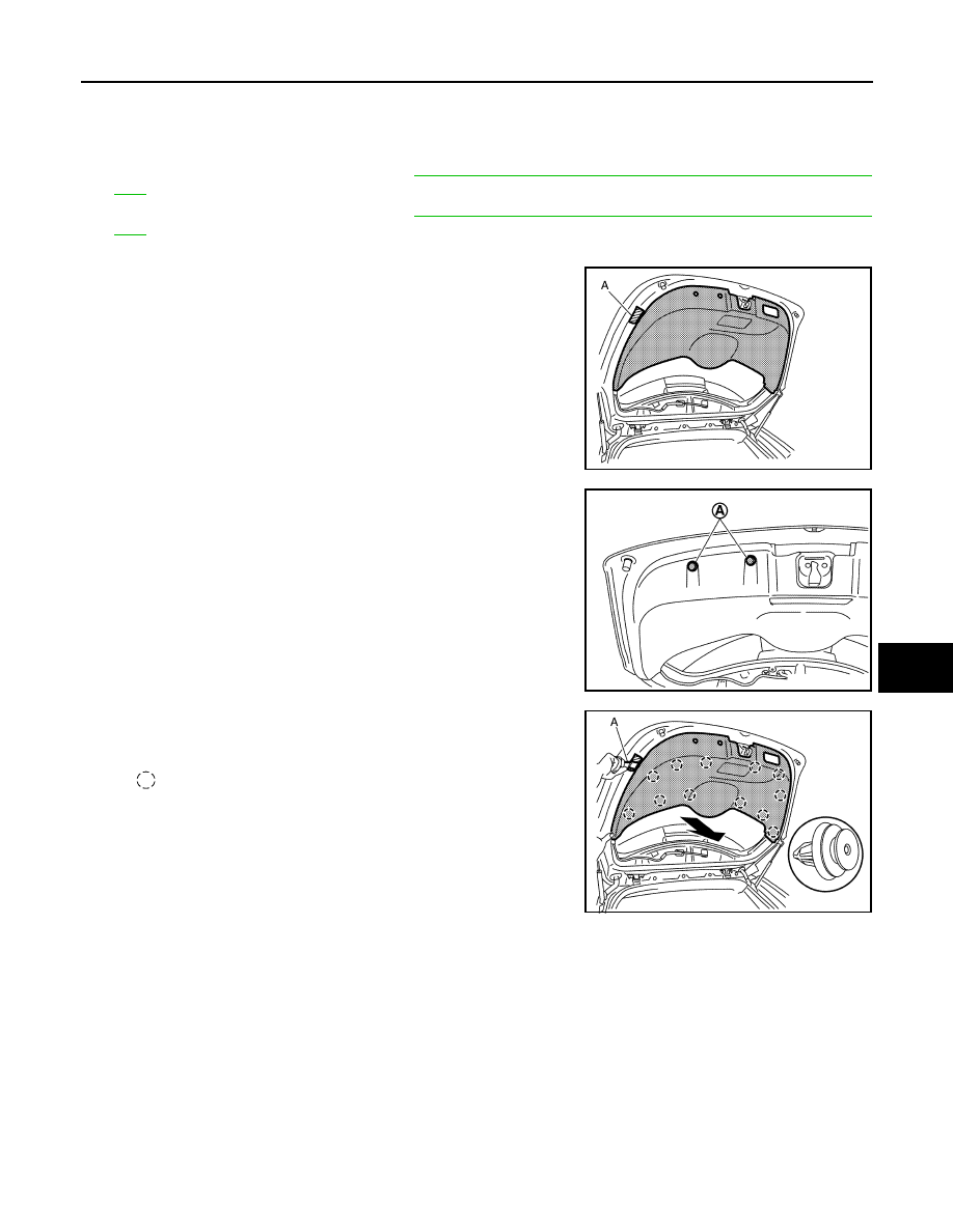
4. Remove back door finisher.
a. Apply protective tape (A) on the parts to protect it from damage.

b. Remove back door lower fixing clips (A).

c. Disengage back door lower finisher fixing clips with a suitable

tool (A), and then remove back door lower finisher.

INATALLATION

Note the following item, and install in the reverse order of removal.

CAUTION:

When installing, check in advance that clips are accurately aligned with the holes on back door side,

and then install by pressing in.

EMERGENCY LID
EMERGENCY LID : Removal and Installation

INFOID:0000000010119694

CAUTION:

When removing, always use a suitable tool that is made of plastic to prevent damage to the parts.

REMOVAL

1. Fully open back door.

JMJIA6965ZZ

JMJIA5157ZZ

: Clip

JMJIA6987ZZ

INT-50

< REMOVAL AND INSTALLATION >

BACK DOOR TRIM

2. Remove emergency lid.
a. Apply protective tape (A) on the parts to protect it from damage.

b. Disengage emergency lid fixing pawls with a suitable tool (A),

and then remove emergency lid.

INSTALLATION

Install in the reverse order of removal.

JMJIA6966ZZ

: Pawl

JMJIA6988ZZ

IP-1

BODY INTERIOR

C

D

E

F

G

H

I

K

L

M

SECTION 

IP

A

B

IP

N

O

P

CONTENTS

INSTRUMENT PANEL

PRECAUTION ...............................................

2

PRECAUTIONS ...................................................

2

Precaution for Technicians Using Medical Electric 

......

2

Point to Be Checked Before Starting Maintenance 
Work ........................................................................
..

2

Precaution for Removing 12V Battery .......................

2

Precaution for Supplemental Restraint System 
(SRS) "AIR BAG" and "SEAT BELT PRE-TEN-
SIONER" .................................................................
..

3

Precaution for Work  ..................................................

3

PREPARATION ............................................

5

PREPARATION ...................................................

5

Special Service Tool  .................................................

5

Commercial Service Tools .......................................

5

CLIP LIST  ............................................................

6

Descriptions for Clips  ................................................

6

SYMPTOM DIAGNOSIS  ..............................

10

SQUEAK AND RATTLE TROUBLE DIAG-
NOSES ..............................................................

10

Work Flow ................................................................

10

Generic Squeak and Rattle Troubleshooting ...........

11

Diagnostic Worksheet ..............................................

14

REMOVAL AND INSTALLATION ...............

16

INSTRUMENT PANEL ASSEMBLY  .................

16

Exploded View .........................................................

16

Removal and Installation  .........................................

17

CENTER CONSOLE ASSEMBLY  ....................

28

Exploded View .........................................................

28

Removal and Installation  .........................................

28

Disassembly and Assembly .....................................

31

IP-2

< PRECAUTION >

PRECAUTIONS

PRECAUTION

PRECAUTIONS

Precaution for Technicians Using Medical Electric

INFOID:0000000010120149

OPERATION PROHIBITION

WARNING:

• Parts with strong magnet is used in this vehicle. 

• Technicians using a medical electric device such as pacemaker must never perform operation on the

vehicle, as magnetic field can affect the device function by approaching to such parts.

NORMAL CHARGE PRECAUTION

WARNING:

• If a technician uses a medical electric device such as an implantable cardiac pacemaker or an

implantable cardioverter defibrillator, the possible effects on the devices must be checked with the

device manufacturer before starting the charge operation.

• As radiated electromagnetic wave generated by PDM (Power Delivery Module) at normal charge

operation may affect medical electric devices, a technician using a medical electric device such as

implantable cardiac pacemaker or an implantable cardioverter defibrillator must not approach motor

room [PDM (Power Delivery Module)] at the hood-opened condition during normal charge operation.

PRECAUTION AT TELEMATICS SYSTEM OPERATION

WARNING:

• If a technician uses implantable cardiac pacemaker or implantable cardioverter defibrillator (ICD),

avoid the device implanted part from approaching within approximately 220 mm (8.66 in) from inte-

rior/exterior antenna.

• The electromagnetic wave of TCU might affect the function of the implantable cardiac pacemaker or

the implantable cardioverter defibrillator (ICD), when using the service, etc.

• If a technician uses other medical electric devices than implantable cardiac pacemaker or implant-

able cardioverter defibrillator (ICD), the electromagnetic wave of TCU might affect the function of the

device. The possible effects on the devices must be checked with the device manufacturer before

TCU use.

PRECAUTION AT INTELLIGENT KEY SYSTEM OPERATION

WARNING:

• If a technician uses implantable cardiac pacemaker or implantable cardioverter defibrillator (ICD),

avoid the device implanted part from approaching within approximately 220 mm (8.66 in) from inte-

rior/exterior antenna.

• The electromagnetic wave of Intelligent Key might affect the function of the implantable cardiac

pacemaker or the implantable cardioverter defibrillator (ICD), at door operation, at each request

switch operation, or at engine starting.

• If a technician uses other medical electric devices than implantable cardiac pacemaker or implant-

able cardioverter defibrillator (ICD), the electromagnetic wave of Intelligent Key might affect the

function of the device. The possible effects on the devices must be checked with the device manu-

facturer before Intelligent Key use.

Point to Be Checked Before Starting Maintenance Work

INFOID:0000000010120150

The high voltage system may starts automatically. It is required to check that the timer air conditioner

and timer charge (during EVSE connection) are not set before starting maintenance work.

NOTE:

If the timer air conditioner or timer charge (during EVSE connection) is set, the high voltage system starts

automatically even when the power switch is in OFF state.

Precaution for Removing 12V Battery

INFOID:0000000010120151

1. Check that EVSE is not connected.

NOTE:

If EVSE is connected, the air conditioning system may be automatically activated by the timer A/C func-

tion.


Content   ..  874  875  876  877   ..