Nissan Leaf. Manual - part 719


  Index      Nissan     Nissan Leaf (2011-2014 year) - Service and Repair Manual


Search            


Content   ..  717  718  719  720   ..


Nissan Leaf. Manual - part 719


GW-24

< REMOVAL AND INSTALLATION >

REAR DOOR GLASS

7. Operate the power window switch to lower the rear door glass.
8. Remove rear door glass run from partition sash.
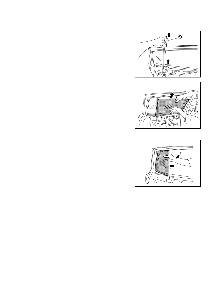
9. Pull partition sash (1) out of the rear door panel to remove, as

shown in the figure.

10. Remove rear door glass from the rear door panel, as shown in

the figure.

11. Remove partition glass.
a. Slide partition glass toward the direction of arrow 1.
b. Pull partition glass toward the direction of arrow 2 to remove.

INSTALLATION

Installation is in the reverse order of removal.

Inspection and Adjustment

INFOID:0000000010119169

FITTING INSPECTION

• Check that the glass is fit securely into the sash groove.

• Lower the glass slightly [approximately 10 to 20 mm (0.394 to 0.787 in)], and check that the clearance to the

sash is parallel. If the clearance between the glass and sash is not parallel, loosen the regulator bolts, guide

rail bolts and glass bolts to correct the glass position.

JMKIA6428ZZ

JMKIA6429ZZ

JMKIA6430ZZ

REAR REGULATOR

GW-25

< REMOVAL AND INSTALLATION >

C

D

E

F

G

H

I

J

L

M

A

B

GW

N

O

P

REAR REGULATOR

Exploded View

INFOID:0000000010119170

Removal and Installation

INFOID:0000000010119171

REMOVAL

1. Remove rear door glass. Refer to 

GW-23, "Removal and Installation"

.

2. Disconnect the power window motor harness connector.

1.

Rear door panel

2.

Rear door glass run

3.

Sealing screen

4.

Rear door regulator

5.

Power window motor

6.

Partition glass

7.

Partition sash

8.

Rear door glass

Front

JMKIA6426ZZ

GW-26

< REMOVAL AND INSTALLATION >

REAR REGULATOR

3. Remove the rear door regulator assembly bolts and nuts, then

remove rear door regulator assembly from door panel, as shown

in the figure.

INSTALLATION

Installation is in the reverse order of removal.

Disassembly and Assembly

INFOID:0000000010119172

DISASSEMBLY

Remove the power window motor from the rear door regulator.

INSPECTION AFTER REMOVAL

Check the rear door regulator assembly for the following items. Replace or grease it if a malfunction is

detected.

• Wire wear

• Regulator deformation

ASSEMBLY

Assembly is in the reverse order of disassembly.

Inspection and Adjustment

INFOID:0000000010119173

Inspection after removal

Check the rear regulator assembly for the following items. Replace or grease it if a malfunction is detected.

• Wire wear

• Rear regulator deformation

• Grease condition for each sliding part

FITTING INSPECTION

• Check that the glass is fit securely into the sash groove.

• Lower the glass slightly [approximately 10 to 20 mm (0.394 to 0.787 in)], and check that the clearance to the

sash is parallel. If the clearance between the glass and sash is not parallel, loosen the regulator bolts, guide

rail bolts and glass bolts to correct the glass position.

JMKIA6431ZZ

HA-1

VENTILATION, HEATER & AIR CONDITIONER

C

D

E

F

G

H

J

K

L

M

SECTION 

HA

A

B

HA

N

O

P

CONTENTS

HEATER & AIR CONDITIONING SYSTEM

WITH HEAT PUMP SYSTEM

PRECAUTION ...............................................

4

PRECAUTIONS ...................................................

4

Precaution for Technicians Using Medical Electric 

......

4

Point to Be Checked Before Starting Maintenance 
Work ........................................................................
..

4

Precaution for Supplemental Restraint System 
(SRS) "AIR BAG" and "SEAT BELT PRE-TEN-
SIONER" .................................................................
..

4

Precaution for Procedure without Cowl Top Cover ......

5

High Voltage Precautions ..........................................

5

Precaution for Removing 12V Battery .......................

7

Precautions for Service Work of Cooler System  .......

8

Service Equipment  ..................................................

10

PREPARATION ...........................................

12

PREPARATION ..................................................

12

Commercial Service Tools  ......................................

12

Oil and Grease  ........................................................

14

SYSTEM DESCRIPTION  .............................

15

COMPONENT PARTS  .......................................

15

REFRIGERATION SYSTEM ......................................

15

REFRIGERATION SYSTEM : Component Parts 
Location ...................................................................

15

HEATING AND COOLING UNIT ASSEMBLY  ..........

16

HEATING AND COOLING UNIT ASSEMBLY : 
Heating and Cooling Unit ........................................

16

HEATING AND COOLING UNIT ASSEMBLY : 
Evaporator ...............................................................

16

HEATING AND COOLING UNIT ASSEMBLY : In-
ner condenser  .........................................................

16

Condenser ...............................................................

16

Electric Compressor ................................................

17

Orifice ......................................................................

19

Accumulator ............................................................

19

Refrigerant and Compressor Oil ..............................

20

High Voltage Warning Label ....................................

20

SYSTEM ............................................................

21

REFRIGERATION SYSTEM  ......................................

21

REFRIGERATION SYSTEM : System Diagram ......

21

REFRIGERATION SYSTEM : System Description 

....

21

HEATING SYSTEM ....................................................

22

HEATING SYSTEM : System Diagram  ...................

22

HEATING SYSTEM : System Description ...............

22

BASIC INSPECTION  ...................................

24

DIAGNOSIS AND REPAIR WORK FLOW  .......

24

Workflow ..................................................................

24

REFRIGERANT .................................................

26

Description ...............................................................

26

Check Refrigerant Leakage .....................................

26

Recycle Refrigerant  .................................................

27

Charge Refrigerant  ..................................................

28

LUBRICANT ......................................................

29

Description ...............................................................

29

Inspection ................................................................

29

Perform Lubricant Return Operation  .......................

29

Lubricant Adjusting Procedure for Components 
Replacement Except Compressor ...........................

29

Lubricant Adjusting Procedure for Compressor 
Replacement ...........................................................

30

PERFORMANCE TEST  ....................................

31

Inspection ................................................................

31

SYMPTOM DIAGNOSIS  ..............................

34

REFRIGERATION SYSTEM SYMPTOMS ........

34

Trouble Diagnosis For Unusual Pressure ................

34

Symptom Table  .......................................................

34


Content   ..  717  718  719  720   ..