Nissan Leaf. Manual - part 686
FRONT DRIVE SHAFT
FAX-25
< UNIT DISASSEMBLY AND ASSEMBLY >
C
E
F
G
H
I
J
K
L
M
A
B
FAX
N
O
P
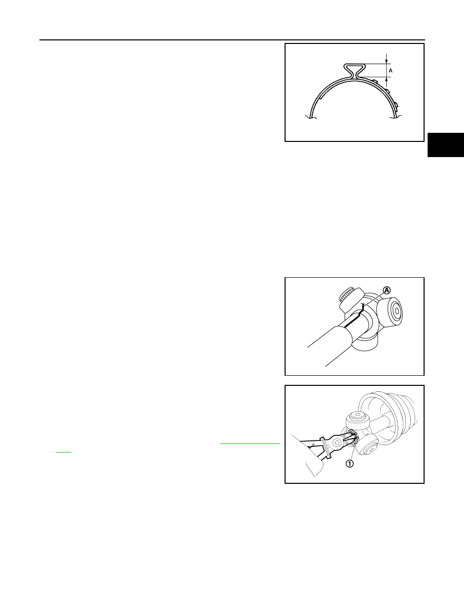
• Secure boot band so that dimension (A) meets the specifi-
cation as shown in the figure.
12. Check that displacement does not occur when boot is rotated
with the joint sub-assembly and shaft fixed.
CAUTION:
• Reinstall them using boot bands when boot installation
positions become incorrect.
• Never reuse boot band.
REDUCTION GEAR SIDE
REDUCTION GEAR SIDE : Disassembly and Assembly
INFOID:0000000010121671
DISASSEMBLY
Left Side
1. Fix shaft with a vise.
CAUTION:
Protect shaft using aluminum or copper plates when fixing with a vise.
2. Remove boot bands, and then remove boot from housing.
3. Put matching marks on housing and shaft, and then pull out housing from shaft.
CAUTION:
Use paint or an equivalent for matching marks. Never scratch the surfaces.
4. Put matching marks (A) on the spider assembly and shaft.
CAUTION:
Use paint or an equivalent for matching marks. Never
scratch the surfaces.
5. Remove snap ring (1), and then remove spider assembly from
shaft.
6. Remove boot from shaft.
7. Remove dust shield from housing.
8. Remove circular clip from housing.
9. Perform inspection after disassembly. Refer to
Right Side
1. Fix shaft with a vise.
CAUTION:
Protect shaft using aluminum or copper plates when fixing with a vise.
2. Remove boot bands, and then remove boot from housing.
3. Put matching marks on housing and shaft, and then pull out housing from shaft.
CAUTION:
Use paint or an equivalent for matching marks. Never scratch the surfaces.
A
: 7.0 mm (0.276 in) or less.
JPDIF0268ZZ
JPDIF0006ZZ
JPDIF0014ZZ