Nissan Leaf. Manual - part 685


  Index      Nissan     Nissan Leaf (2011-2014 year) - Service and Repair Manual


Search            


Content   ..  683  684  685  686   ..


Nissan Leaf. Manual - part 685


FRONT DRIVE SHAFT

FAX-21

< REMOVAL AND INSTALLATION >

C

E

F

G

H

I

J

K

L

M

A

B

FAX

N

O

P

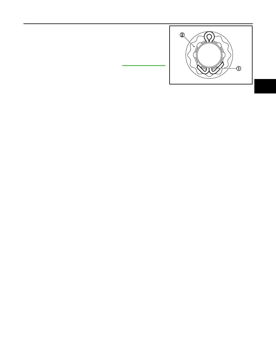
• When installing a cotter pin (1) and nut retainer (2), securely bend

the basal portion to prevent rattles.

CAUTION:

Do not reuse cotter pin.

• Perform the final tightening of each of parts under unladen condi-

tions, which were removed when removing wheel hub assembly

and steering knuckle. 

• Perform inspection after installation. Refer to 

FAX-31, "Inspection"

.

JPDIF0295ZZ

FAX-22

< UNIT DISASSEMBLY AND ASSEMBLY >

FRONT DRIVE SHAFT

UNIT DISASSEMBLY AND ASSEMBLY

FRONT DRIVE SHAFT

Exploded View

INFOID:0000000010121669

LEFT SIDE

RIGHT SIDE

1.

Circular clip

2.

Dust shield

3.

Housing

4.

Snap ring

5.

Spider assembly

6.

Boot band

7.

Boot

8.

Shaft

9.

Joint sub-assembly

: Wheel side

: Always replace after every disassembly.

: Fill NISSAN Genuine grease or equivalent.

JPDIF0316GB

1.

Joint sub-assembly

2.

Circular clip

3.

Boot band

4.

Boot

5.

Shaft

6.

Spider assembly

AWDIA1095ZZ

FRONT DRIVE SHAFT

FAX-23

< UNIT DISASSEMBLY AND ASSEMBLY >

C

E

F

G

H

I

J

K

L

M

A

B

FAX

N

O

P

WHEEL SIDE
WHEEL SIDE : Disassembly and Assembly

INFOID:0000000010121670

DISASSEMBLY

1. Fix shaft with a vise.

CAUTION:

Protect shaft when fixing with a vise using aluminum or copper plates.

2. Remove boot bands, and then remove boot from joint sub-assembly.
3. Screw drive shaft puller (A) (commercial service tool) into joint

sub-assembly screw part to a length of 30 mm (1.18 in) or more.

Support drive shaft with one hand and pull out joint sub-assem-

bly from shaft.

CAUTION:

• Align drive shaft puller and drive shaft and remove them

by pulling firmly and uniformly.

• If joint sub-assembly cannot be removed after five or

more unsuccessful attempts, replace shaft and joint sub

assembly as a set.

4. Remove circular clip from shaft.
5. Remove boot from shaft.
6. Perform inspection after disassembly. Refer to 

FAX-31, "Inspection"

.

ASSEMBLY

1. Clean the old grease on joint sub-assembly with paper waste.
2. Fill serration slot joint sub-assembly (1) with NISSAN genuine

grease or equivalent until the serration slot and ball groove

become full to the brim.

CAUTION:

After applying grease, use a paper waste to wipe off old

grease that has oozed out.

3. Install boot and boot bands to shaft.

CAUTION:

• Wrap serration on shaft with tape (A) to protect the boot

from damage.

• Never reuse boot and boot band.

4. Remove the tape wrapped around the serration on shaft.

7.

Snap ring

8.

Housing

9.

Dust shield

10. Support bearing

Wheel side

JPDIG0151ZZ

JPDIF0008ZZ

JPDIF0009ZZ

FAX-24

< UNIT DISASSEMBLY AND ASSEMBLY >

FRONT DRIVE SHAFT

5. Position the circular clip (1) on groove at the shaft edge.

CAUTION:

Never reuse circular clip.

NOTE:

Drive joint inserter is recommended when installing circular clip.

6. Align both center axles of the shaft edge and joint sub-assembly.

Then assemble shaft with joint sub-assembly holding circular

clip.

7. Install joint sub-assembly to shaft using plastic hammer.

CAUTION:

• Check circular clip is properly positioned on groove of the

joint sub-assembly.

• Confirm that joint sub-assembly is correctly engaged

while rotating drive shaft.

8. Apply the specified amount of grease into the boot inside from

large diameter side of boot.

9. Install the boot securely into grooves (indicated by “*” marks)

shown in the figure.

CAUTION:

If grease adheres to the boot mounting surface (indicated

by “*” marks) on the shaft or joint sub-assembly, boot may

be removed. Remove all grease from the boot mounting

surface.

10. To prevent the deformation of the boot, adjust the boot installa-

tion length to the specified value by inserting the suitable tool

into inside of the boot from the large diameter side of the boot

and discharging the inside air.

CAUTION:

• If the boot installation length exceeds the standard, it may cause breakage of the boot.

• Be careful not to touch the inside of the boot with a tip of tool.

11. Secure the large and small ends of the boot with boot bands

using the boot band crimping tool (A) [SST: KV40107300 ( —

)].

CAUTION:

• Never reuse boot band.

JPDIF0305ZZ

Grease amount

: Refer to 

FAX-32, "Drive Shaft"

.

RAC0049D

L

: Boot installation length

Boot installation length : Refer to 

FAX-32, "Drive Shaft"

.

JSDIA2261ZZ

JPDIF0012ZZ


Content   ..  683  684  685  686   ..