Nissan Leaf. Manual - part 606


  Index      Nissan     Nissan Leaf (2011-2014 year) - Service and Repair Manual


Search            


Content   ..  604  605  606  607   ..


Nissan Leaf. Manual - part 606


DIAGNOSIS SYSTEM (BCM)

EXL-25

< SYSTEM DESCRIPTION >

[LED HEADLAMP]

C

D

E

F

G

H

I

J

K

M

A

B

EXL

N

O

P

*: Initial setting

FLASHER
FLASHER : CONSULT Function (BCM - FLASHER)

INFOID:0000000010519552

DATA MONITOR

ACTIVE TEST

WORK SUPPORT

CUSTOM A/LIGHT SETTING
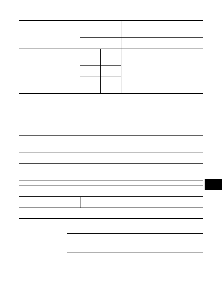
MODE4

Less sensitive than normal setting (turns ON later).

MODE3

More sensitive than MODE2.

MODE2

More sensitive than normal setting (turns ON earlier).

MODE1*

Normal setting.

ILL DELAY SET

MODE 8

180 sec.

Autolamp delay timer operation time.

MODE 7

150 sec.

MODE 6

120 sec.

MODE 4

90 sec.

MODE 5

60 sec.

MODE 3

30 sec.

MODE 2

OFF

MODE 1*

45 sec.

Support Item

Setting

Description

Monitor Item [Unit]

Description

REQ SW -DR [On/Off]

Indicates condition of door request switch LH.

REQ SW -AS [On/Off]

Indicates condition of door request switch RH.

PUSH SW [On/Off]

Indicates condition of power switch.

TURN SIGNAL R [On/Off]

Indicates condition of turn signal function of combination switch.

TURN SIGNAL L [On/Off]

HAZARD SW [On/Off]

Indicates condition of hazard switch.

RKE-LOCK [On/Off]

Indicates condition of lock signal from Intelligent Key.

RKE-UNLOCK [On/Off]

Indicates condition of unlock signal from Intelligent Key.

RKE-PANIC [On/Off]

Indicates condition of panic alarm signal from Intelligent Key.

Test Item

Description

FLASHER

This test is able to check turn signal lamp operation [Off/LH/RH].

Support Item

Setting

Description

HAZARD ANSWER BACK

Lock/Unlock

Hazard warning lamp answer back for LOCK and UNLOCK with request switch or 
Intelligent Key.

Unlock Only

Hazard warning lamp answer back for UNLOCK only with request switch or Intelli-
gent Key.

Lock Only

Hazard warning lamp answer back for LOCK only with request switch or Intelligent 
Key.

Off

Hazard warning lamp answer back OFF.

EXL-26

< SYSTEM DESCRIPTION >

[LED HEADLAMP]

DIAGNOSIS SYSTEM (IPDM E/R)

DIAGNOSIS SYSTEM (IPDM E/R)

Diagnosis Description

INFOID:0000000010519553

AUTO ACTIVE TEST

Description

In auto active test mode, the IPDM E/R sends a drive signal to the following systems to check their operation.

• Rear window defogger

• Front wiper motor

• Parking lamp

• License plate lamp

• Tail lamp

• Front fog lamp

• Side marker lamp

• Headlamp (LO, HI)

Operation Procedure

NOTE:

Never perform auto active test in the following conditions.

• CONSULT is connected.

• Passenger door is open.
1. Turn the power switch OFF.
2. Turn the power switch ON, and within 20 seconds, press the driver door switch 10 times. Then turn the

power switch OFF.

3. Turn the power switch ON within 10 seconds. After that the horn sounds once and the auto active test

starts.

NOTE:

Never depress brake pedal while operating power switch so that auto active test is not activated.

4. After a series of the following operations is repeated 3 times, auto active test is completed.
NOTE:

• When auto active test mode has to be cancelled halfway through test, turn the power switch OFF.

• When auto active test is not activated, door switch may be the cause. Check door switch. Refer to 

DLK-102,

"Component Function Check"

.

Inspection in Auto Active Test Mode

When auto active test mode is actuated, the following operation sequence is repeated 3 times.

Operation 
sequence

Inspection location

Operation

1

Rear window defogger

10 seconds

2

Front wiper motor

LO for 5 seconds 

→ HI for 5 seconds

3

• Parking lamp
• License plate lamp
• Tail  lamp
• Front  fog  lamp
• Side marker lamp

10 seconds

4

Headlamp

LO for 10 seconds 

→HI ON ⇔ OFF 5 times

DIAGNOSIS SYSTEM (IPDM E/R)

EXL-27

< SYSTEM DESCRIPTION >

[LED HEADLAMP]

C

D

E

F

G

H

I

J

K

M

A

B

EXL

N

O

P

Concept of auto active test

• IPDM E/R starts the auto active test with the door switch signals transmitted by BCM via CAN communica-

tion. Therefore, the CAN communication line between IPDM E/R and BCM is considered normal if the auto

active test starts successfully.

• The auto active test facilitates troubleshooting if any systems controlled by IPDM E/R cannot be operated.

Diagnosis chart in auto active test mode

CONSULT Function (IPDM E/R)

INFOID:0000000010519554

APPLICATION ITEM

CONSULT performs the following functions via CAN communication with IPDM E/R.

SELF DIAGNOSTIC RESULT

Refer to 

PCS-18, "DTC Index"

.

DATA MONITOR

JMMIA0657GB

Symptom

Inspection contents

Possible cause

Rear window defogger does not operate

Perform auto active test.
Does the rear window defogger 
operate?

YES

BCM signal input circuit

NO

• Rear window defogger
• Rear window defogger ground circuit
• Harness or connector between IPDM E/R 

and rear window defogger

• IPDM  E/R

Any of the following components do not 
operate

• Parking  lamp
• License plate lamp
• Tail lamp
• Front fog lamp
• Headlamp (HI, LO)
• Side marker lamp
• Front wiper motor

Perform auto active test.
Does the applicable system op-
erate?

YES

BCM signal input circuit

NO

• Lamp or motor
• Lamp or motor ground circuit
• Harness or connector between IPDM E/R 

and applicable system

• IPDM  E/R

Direct Diagnostic Mode

Description

Ecu Identification

The IPDM E/R part number is displayed.

Self Diagnostic Result

The IPDM E/R self diagnostic results are displayed.

Data Monitor

The IPDM E/R input/output data is displayed in real time.

Active Test

The IPDM E/R activates outputs to test components.

CAN Diag Support Mntr

The result of transmit/receive diagnosis of CAN communication is displayed.

EXL-28

< SYSTEM DESCRIPTION >

[LED HEADLAMP]

DIAGNOSIS SYSTEM (IPDM E/R)

ACTIVE TEST

CAN DIAG SUPPORT MNTR

Refer to 

LAN-14, "CAN Diagnostic Support Monitor"

.

Monitor Item [Unit]

Main

Signals

Description

TAIL&CLR REQ [On/Off]

×

Indicates position light request signal received from BCM on CAN communica-
tion line

HL LO REQ [On/Off]

×

Indicates low beam request signal received from BCM on CAN communication 
line

HL HI REQ [On/Off]

×

Indicates high beam request signal received from BCM on CAN communication 
line

FR FOG REQ [On/Off]

×

Indicates front fog light request signal received from BCM on CAN communica-
tion line

FR WIP REQ [Stop/1LOW/Low/Hi]

×

Indicates front wiper request signal received from BCM on CAN communication 
line

WIP AUTO STOP [STOP P/ACT P]

×

Indicates condition of front wiper auto stop signal

WIP PROT [Off/BLOCK]

×

Indicates condition of front wiper fail-safe operation

IGN RLY1 -REQ [On/Off]

Indicates power switch ON signal received from BCM on CAN communication 
line

IGN RLY [On/Off]

×

Indicates condition of ignition relay-1

PUSH SW [On/Off]

Indicates condition of power switch

DETENT SW [On/Off]

Indicates condition of shift position (park position switch)

DTRL REQ [Off]

Indicates daytime light request signal received from BCM on CAN communica-
tion line

HOOD SW [On/Off]

Indicates condition of hood switch

THFT HRN REQ [On/Off]

Indicates theft warning horn request signal received from BCM on CAN commu-
nication line

HORN CHIRP [On/Off]

Indicates horn reminder signal received from BCM on CAN communication line

Test item

Description

HORN

This test is able to check horn operation [On].

REAR DEFOGGER

This test is able to check rear window defogger operation [On/Off].

FRONT WIPER

This test is able to check wiper motor operation [Hi/Lo/Off].

EXTERNAL LAMPS

This test is able to check external lamp operation [Fog/Hi/Lo/TAIL/Off].


Content   ..  604  605  606  607   ..