Nissan Leaf. Manual - part 605


  Index      Nissan     Nissan Leaf (2011-2014 year) - Service and Repair Manual


Search            


Content   ..  603  604  605  606   ..


Nissan Leaf. Manual - part 605


SYSTEM

EXL-21

< SYSTEM DESCRIPTION >

[LED HEADLAMP]

C

D

E

F

G

H

I

J

K

M

A

B

EXL

N

O

P

FRONT FOG LAMP SYSTEM
FRONT FOG LAMP SYSTEM : System Description

INFOID:0000000010121327
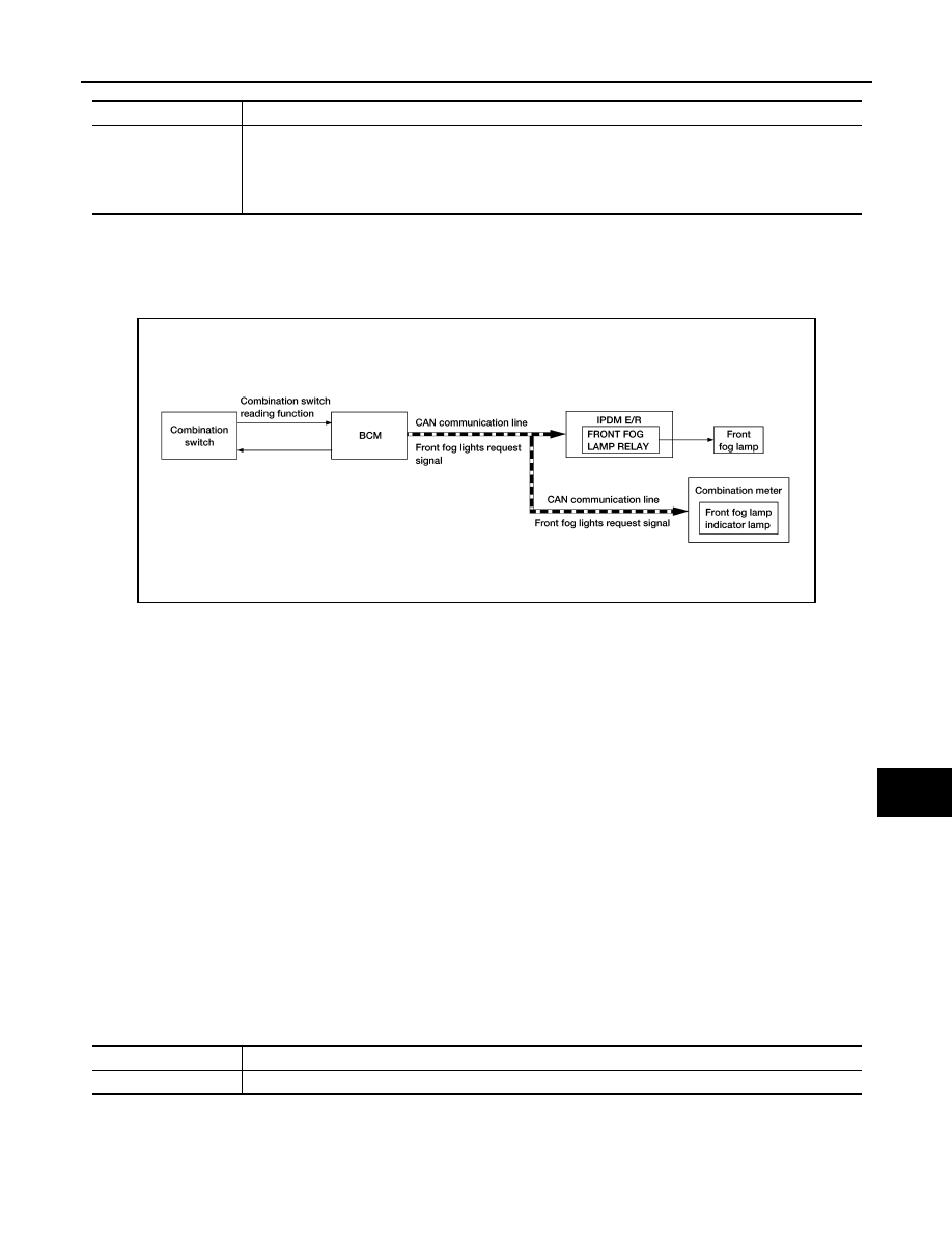
SYSTEM DIAGRAM

OUTLINE

Front fog lamp is controlled by combination switch reading function, front fog lamp control function of BCM,

and relay control function of IPDM E/R.

FRONT FOG LAMP OPERATION 

• BCM detects the combination switch condition by the combination switch reading function.

• BCM transmits the front fog lights request signal to IPDM E/R and the combination meter via CAN communi-

cation according to the front fog lamp ON condition.

Front fog lamp ON condition

- Front fog lamp switch ON, and any of the following condition is satisfied.(except for the high beam ON):

• Lighting switch 2ND

• Lighting switch AUTO and the power switch ON

IPDM E/R turns the integrated front fog lamp relay ON, and turns the front fog lamp ON according to the front

fog lights request signal.

Combination meter turns the front fog lamp indicator lamp ON according to the front fog lights request signal.

FRONT FOG LAMP SYSTEM : Fail-Safe

INFOID:0000000010121329

CAN COMMUNICATION CONTROL

When CAN communication with BCM is impossible, IPDM E/R performs fail-safe control. After CAN communi-

cation recovers normally, it also returns to normal control.

If No CAN Communication Is Available With BCM

EXTERIOR LAMP BATTERY SAVER SYSTEM

Control part

Fail-safe operation

• Parking lamp
• License plate lamp
• Illumination
• Tail  lamp
• Side marker lamp

• Turns ON the tail lamp relay when the power switch is turned ON
• Turns OFF the tail lamp relay when the power switch is turned OFF

ALLIA1449GB

Control part

Fail-safe operation

Front fog lamp

Front fog lamp relay OFF

EXL-22

< SYSTEM DESCRIPTION >

[LED HEADLAMP]

SYSTEM

EXTERIOR LAMP BATTERY SAVER SYSTEM : System Description

INFOID:0000000010121330

SYSTEM DIAGRAM

OUTLINE

• Exterior lamp battery saver system is controlled by each function of BCM and IPDM E/R.

Control by BCM:

- Combination switch reading function

- Headlamp control function

- Exterior lamp battery saver function

Control by IPDM E/R:

- Relay control function

• BCM turns the exterior lamps* OFF after a period of time to prevent the battery from over-discharge when

the power switch is turned OFF with the exterior lamps ON.

*: Headlamp (LO/HI), parking lamp, tail lamp, side marker lamp, license plate lamp and front fog lamp

EXTERIOR LAMP BATTERY SAVER ACTIVATION

BCM activates the timer and turns the exterior lamp OFF 5 minutes after the power switch is turned from ON

→ OFF with the exterior lamps ON. 

NOTE:

• Headlamp control function turns the exterior lamps ON normally when the power switch is turned ACC or 

set the vehicle to READY (both before and after the exterior lamp battery saver is turned OFF).

• The timer starts at the time that the lighting switch is turned from OFF 

→ 1ST or 2ND with the exterior lamps

OFF.

ALLIA1450GB

DIAGNOSIS SYSTEM (BCM)

EXL-23

< SYSTEM DESCRIPTION >

[LED HEADLAMP]

C

D

E

F

G

H

I

J

K

M

A

B

EXL

N

O

P

DIAGNOSIS SYSTEM (BCM)

COMMON ITEM
COMMON ITEM : CONSULT Function (BCM - COMMON ITEM)

INFOID:0000000010519550

APPLICATION ITEM

CONSULT performs the following functions via CAN communication with BCM.

SYSTEM APPLICATION

BCM can perform the following functions.

HEADLAMP

Direct Diagnostic Mode

Description

Ecu Identification

The BCM part number is displayed.

Self Diagnostic Result

The BCM self diagnostic results are displayed.

Data Monitor

The BCM input/output data is displayed in real time.

Active Test

The BCM activates outputs to test components.

Work support

The settings for BCM functions can be changed.

Configuration

• The vehicle specification can be read and saved.
• The vehicle specification can be written when replacing BCM.

CAN Diag Support Mntr

The result of transmit/receive diagnosis of CAN communication is displayed.

System

Sub System

Direct Diagnostic Mode

E

cu

 Id

en

tifi

ca

tio

n

Se

lf Di

ag

no

st

ic Re

su

lt

Da

ta

 Mo

ni

tor

A

cti

ve

 T

est

W

o

rk support

Co

nf

igu

rat

ion

CA

N Diag

 Su

pp

ort Mn

tr

Door lock

DOOR LOCK

×

×

×

×

Rear window defogger

REAR DEFOGGER

×

×

Warning chime

BUZZER

×

×

Interior room lamp timer

INT LAMP

×

×

×

Exterior lamp

HEADLAMP

×

×

×

Wiper and washer

WIPER

×

×

×

Turn signal and hazard warning lamps FLASHER

×

×

×

Air conditioner

AIR CONDITIONER

×

×

Intelligent Key system

INTELLIGENT KEY

×

×

×

×

Combination switch

COMB SW

×

BCM

BCM

×

×

×

×

×

Immobilizer

IMMU

×

×

×

×

Interior room lamp battery saver

BATTERY SAVER

×

×

×

Trunk open

TRUNK

×

Vehicle security system

THEFT ALM

×

×

×

RAP system

RETAINED PWR

×

Signal buffer system

SIGNAL BUFFER

×

TPMS

AIR PRESSURE MONITOR

×

×

×

×

EXL-24

< SYSTEM DESCRIPTION >

[LED HEADLAMP]

DIAGNOSIS SYSTEM (BCM)

HEADLAMP : CONSULT Function (BCM - HEAD LAMP)

INFOID:0000000010519551

DATA MONITOR

ACTIVE TEST

WORK SUPPORT

Monitor Item [Unit]

Description

PUSH SW [On/Off]

Indicates condition of power switch.

ENGINE STATE [Stop/Stall/Crank/Run]

Indicates engine status received from ECM on CAN communication line.

VEH SPEED 1 [km/h]

Indicates vehicle speed signal received from ABS on CAN communication line.

TURN SIGNAL R [On/Off]

Indicates condition of combination switch.

TURN SIGNAL L [On/Off]

TAIL LAMP SW [On/Off]

HI BEAM SW [On/Off]

HEAD LAMP SW 1 [On/Off]

HEAD LAMP SW 2 [On/Off]

PASSING SW [On/Off]

AUTO LIGHT SW [On/Off]

FR FOG SW [On/Off]

DOOR SW-DR [On/Off]

Indicates condition of front door switch LH.

DOOR SW-AS [On/Off]

Indicates condition of front door switch RH.

DOOR SW-RR [On/Off]

Indicates condition of rear door switch RH.

DOOR SW-RL [On/Off]

Indicates condition of rear door switch LH.

DOOR SW-BK [On/Off]

Indicates condition of trunk switch.

OPTI SEN (DTCT) [V]

Indicates outside brightness voltage signal from optical sensor.

OPTI SEN (FILT) [V]

Indicates outside brightness voltage signal from optical sensor filtered by BCM.

Test Item

Description

FR FOG LAMP

This test is able to check front fog lamp operation [On/Off].

HEAD LAMP

This test is able to check headlamp operation [Off/Low/Hi].

ILL DIM SIGNAL

This test is able to check head lamp illumination dimming operation [On/Off].

TAIL LAMP

This test is able to check taillamp operation [Off/On].

Support Item

Setting

Description

AUTO LIGHT LOGIC SET

MODE6

Autolamp function OFF.

MODE5

MODE4

MODE3

Autolamp function ON at twilight.

MODE2

Autolamp function ON at twilight or with wiper LO and HI 
operation.

MODE1*

Autolamp function ON at twilight or with wiper INT, LO and 
HI operation.

BATTERY SAVER SET

Off

Exterior lamp battery saver function OFF.

On*

Exterior lamp battery saver function ON.


Content   ..  603  604  605  606   ..