Nissan Leaf. Manual - part 500
EVC-24
< SYSTEM DESCRIPTION >
COMPONENT PARTS
Synchronization is applied.
For master warning lamp, refer to
MWI-31, "MASTER WARNING LAMP : System Description"
.
OPERATION AT COMBINATION METER CAN COMMUNICATION CUT-OFF OR UNUSUAL SIG-
NAL
For actions on CAN communications blackout in the combination meter, refer to
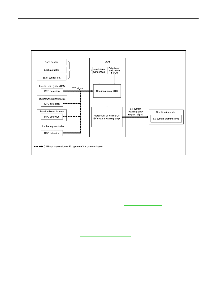
SYSTEM DIAGRAM
SIGNAL PATH
• If VCM detects a malfunction or receives an EV system warning lamp request signal from any other ECUs,
VCM transmits an EV system warning lamp request signal to the combination meter via CAN communica-
tion.
• Combination meter illuminates EV system warning lamp according to the input signal.
LIGHTING CONDITION
When all of the following conditions are satisfied:
• Power switch: ON or READY
• EV system-related DTC is confirmed.
NOTE:
For DTCs that the EV system warning lamp turns ON, refer to
SHUTOFF CONDITION
When any of the following conditions are satisfied:
• Power switch: OFF
• DTC is erased.
NOTE:
• The warning lamp may turn ON even after the power switch is turned OFF, depending on a detected DTC.
• For DTC erasing method, refer to
JSCIA0552GB