Nissan Leaf. Manual - part 499
EVC-20
< SYSTEM DESCRIPTION >
COMPONENT PARTS
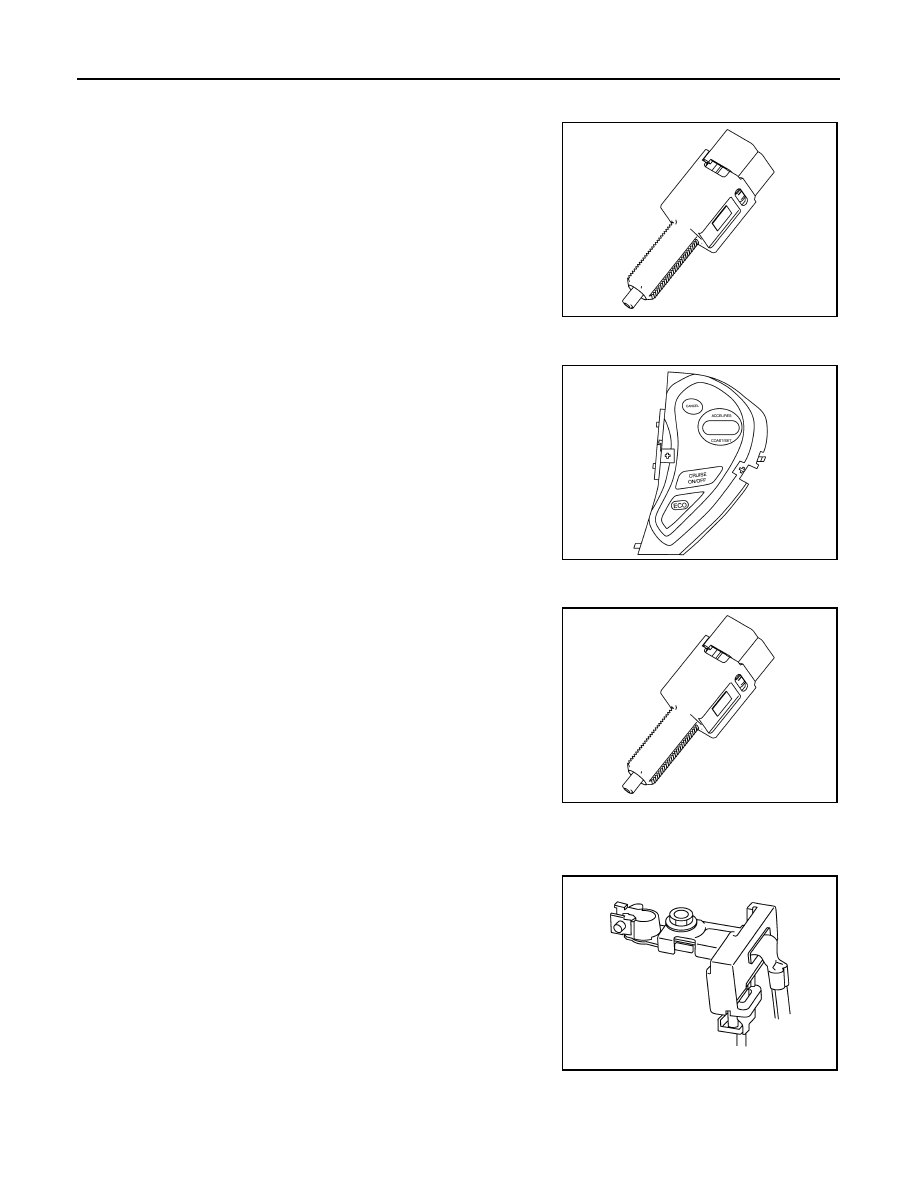
Stop Lamp Switch
INFOID:0000000010120530
The stop lamp switch is installed to the brake pedal bracket. The
switch detects the state of the brake pedal and transmits an ON/OFF
signal to VCM.
The contact of the stop lamp switch is usually open. When the brake
pedal is depressed, it closes and the stop lamp switch signal is
transmitted as a voltage signal.
ASCD Steering Switch
INFOID:0000000010120531
ASCD steering switch has various values of electrical resistance for
each button. VCM reads voltage variation of switch, and determines
which button is operated.
Brake Pedal Position Switch
INFOID:0000000010120532
The brake pedal position switch is installed to the brake pedal
bracket. The switch detects the state of the brake pedal and trans-
mits an ON/OFF signal to VCM.
The contact of the brake pedal position switch is usually closed.
When the brake pedal is depressed, it opens to disconnect the cir-
cuit, and shut off the output voltage. This constitutes an brake pedal
position switch signal.
Battery Current Sensor (With Battery Temperature Sensor)
INFOID:0000000010120533
BATTERY CURRENT SENSOR
The battery current sensor is installed to the negative cable of the
battery. The battery current sensor detects the battery charge/dis-
charge current and transmits signals to VCM. VCM judges the bat-
tery load based on these signals and controls the power generation
by converting the target generation voltage to a power generation
command signal and transmitting it to the DC/DC converter.
CAUTION:
Never connect the electrical component or the ground wire
directly to the battery terminal. The connection causes the mal-
function of the power voltage variable control, and may cause
the battery to discharge.
BATTERY TEMPERATURE SENSOR
Battery temperature sensor is integrated in battery current sensor.
The sensor measures temperature around the battery.
JSBIA0308ZZ
JSCIA0485ZZ
JSBIA0308ZZ
JPBIA3262ZZ