Nissan Leaf. Manual - part 417


  Index      Nissan     Nissan Leaf (2011-2014 year) - Service and Repair Manual


Search            


Content   ..  415  416  417  418   ..


Nissan Leaf. Manual - part 417


RADIATOR CORE SUPPORT

DLK-163

< REMOVAL AND INSTALLATION >

C

D

E

F

G

H

I

J

L

M

A

B

DLK

N

O

P

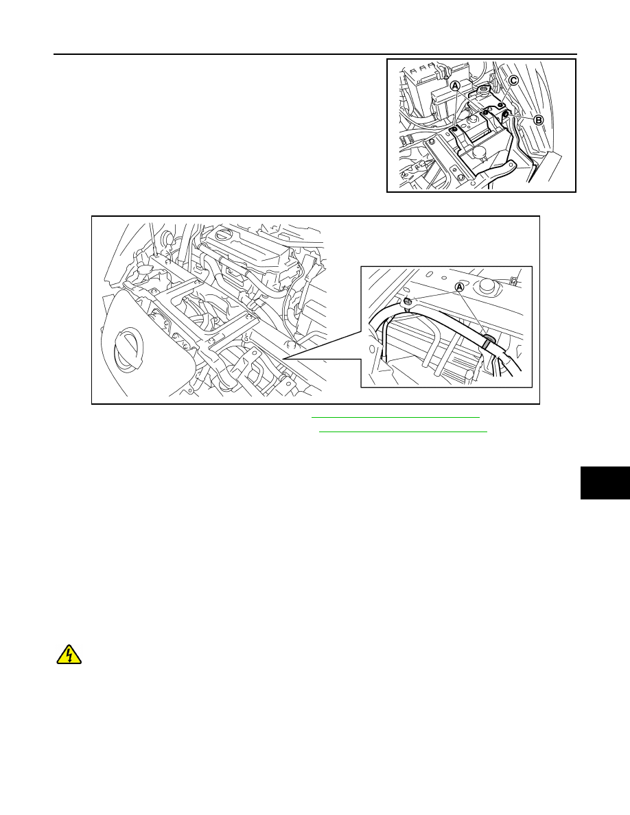
5. Remove reservoir tank bolts (A), air guide (LH) clip (B) and

degas tank bolt (C).

6. Remove harness fixing clips (A).

7. Disconnect quick charge port connector. Refer to 

VC-128, "Removal and Installation"

.

8. Disconnect normal charge port connector. Refer to 

VC-135, "Removal and Installation"

.

9. Remove upper mounting bolts of charge port bracket.
10. Remove lower mounting nuts and bolt of radiator core support lower stay.
11. Move charge port bracket and radiator core support lower stay.
12. Support hood assembly using a suitable tool.

WARNING:

Injury may occur if hood assembly is not supported with appropriate material when removing

hood assembly.

13. Remove radiator core support upper bolts and radiator core support upper.

INSTALLATION

Installation is in the reverse order of removal.

RADIATOR CORE SUPPORT LOWER
RADIATOR CORE SUPPORT LOWER : Removal and Installation

INFOID:0000000010119860

DANGER:

Since hybrid vehicles and electric vehicles contain a high voltage battery, there is the risk of

electric shock, electric leakage, or similar accidents if the high voltage component and vehicle are

handled incorrectly. Be sure to follow the correct work procedures when performing inspection and

maintenance.

WARNING:

• Be sure to remove the service plug in order to disconnect the high voltage circuits before perform-

ing inspection or maintenance of high voltage system harnesses and parts.

• The removed service plug must always be carried in a pocket of the responsible worker or placed in

the tool box during the procedure to prevent the plug from being connected by mistake.

JMKIA6500ZZ

JMKIA9359ZZ

DLK-164

< REMOVAL AND INSTALLATION >

RADIATOR CORE SUPPORT

• Be sure to wear insulating protective equipment consisting of glove, shoes, face shield and glasses

before beginning work on the high voltage system.

• Never allow workers other than the responsible person to touch the vehicle containing high voltage

parts. To keep others from touching the high voltage parts, these parts must be covered with an insu-

lating sheet except when using them.

• Refer to 

GI-34, "High Voltage Precautions"

.

CAUTION:

Never bring the vehicle into the READY status with the service plug removed unless otherwise

instructed in the Service Manual. A malfunction may occur if this is not observed.

REMOVAL

WARNING:

Disconnect the high voltage. Refer to 

GI-33, "How to Disconnect High Voltage"

.

1. Check voltage in high voltage circuit. (Check that condenser are discharged.)
a. Lift up the vehicle and remove the Li-ion battery under covers. refer to 

EVB-181, "Exploded View"

.

b. Disconnect high voltage connector from front side of Li-ion battery. Refer to 

EVB-181, "Removal and

Installation"

.

c.

Measure voltage between high voltage harness terminals.

DANGER:


 Always use protective equipment as touching high

voltage components without using them will cause electro-

cution. (where high voltage might remain/is present on ter-

minals.)

CAUTION:

For voltage measurements, use a tester which can measure to 500V or higher.

2. Remove front bumper fascia, energy absorber, and apron bracket. Refer to 

EXT-13, "Removal and Instal-

lation"

.

3. Remove reservoir tank bolts (A).

Standard

: 5 V or less 

JSAIA1362ZZ

JMKIA6501ZZ

RADIATOR CORE SUPPORT

DLK-165

< REMOVAL AND INSTALLATION >

C

D

E

F

G

H

I

J

L

M

A

B

DLK

N

O

P

4. Remove harness fixing clips (A).

5. Disconnect quick charge port connector. Refer to 

VC-128, "Removal and Installation"

.

6. Disconnect normal charge port connector. Refer to 

VC-135, "Removal and Installation"

.

7. Remove lower mounting bolts of hood lock assembly.
8. Remove upper mounting bolts of charge port bracket.
9. Remove lower mounting nuts and bolt of radiator core support lower stay.
10. Move charge port bracket and radiator core support lower stay.
11. Remove air guides (LH/RH).
12. Use belts (A) to suspend radiator and condenser to prevent

them from falling.

CAUTION:

Do not damage radiator and condenser.

13. Remove front fixing clip of fender protector (LH/RH) from radiator core support lower.
14. Remove radiator core support lower bolts and radiator core support lower.

INSTALLATION

Installation is in the reverse order of removal.

RADIATOR UPPER GRILLE
RADIATOR UPPER GRILLE : Removal and Installation

INFOID:0000000010119861

REMOVAL

Remove radiator upper grille clips and radiator upper grille.

INSTALLATION

Installation in the reverse order of removal.

CHARGE PORT BRACKET
CHARGE PORT BRACKET : Removal and Installation

INFOID:0000000010119862

DANGER:

Since hybrid vehicles and electric vehicles contain a high voltage battery, there is the risk of

electric shock, electric leakage, or similar accidents if the high voltage component and vehicle are

JMKIA9359ZZ

JMKIA6502ZZ

DLK-166

< REMOVAL AND INSTALLATION >

RADIATOR CORE SUPPORT

handled incorrectly. Be sure to follow the correct work procedures when performing inspection and

maintenance.

WARNING:

• Be sure to remove the service plug in order to disconnect the high voltage circuits before perform-

ing inspection or maintenance of high voltage system harnesses and parts.

• The removed service plug must always be carried in a pocket of the responsible worker or placed in

the tool box during the procedure to prevent the plug from being connected by mistake.

• Be sure to wear insulating protective equipment consisting of glove, shoes, face shield and glasses

before beginning work on the high voltage system.

• Never allow workers other than the responsible person to touch the vehicle containing high voltage

parts. To keep others from touching the high voltage parts, these parts must be covered with an insu-

lating sheet except when using them.

• Refer to 

GI-34, "High Voltage Precautions"

.

CAUTION:

Never bring the vehicle into the READY status with the service plug removed unless otherwise

instructed in the Service Manual. A malfunction may occur if this is not observed.

REMOVAL

WARNING:

Disconnect the high voltage. Refer to 

GI-33, "How to Disconnect High Voltage"

.

1. Check voltage in high voltage circuit. (Check that condenser are discharged.)
a. Lift up the vehicle and remove the Li-ion battery under covers. refer to 

EVB-181, "Exploded View"

.

b. Disconnect high voltage connector from front side of Li-ion battery. Refer to 

EVB-181, "Removal and

Installation"

.

c.

Measure voltage between high voltage harness terminals.

DANGER:


 Always use protective equipment as touching high

voltage components without using them will cause electro-

cution. (where high voltage might remain/is present on ter-

minals.)

CAUTION:

For voltage measurements, use a tester which can measure to 500V or higher.

2. Remove charge port hinge assembly. Refer to 

DLK-160, "CHARGE PORT LID HINGE ASSEMBLY :

Removal and Installation"

.

3. Remove quick charge port. Refer to 

VC-128, "Removal and Installation"

.

4. Remove normal charge port. Refer to 

VC-135, "Removal and Installation"

.

5. Remove crash zone sensor. Refer to 

SR-33, "Removal and Installation"

.

6. Remove harness fixing clips (A).

7. Remove charge port bracket bolts and nuts and charge port bracket.

Standard

: 5 V or less 

JSAIA1362ZZ

JMKIA6503ZZ


Content   ..  415  416  417  418   ..