Nissan Leaf. Manual - part 416
CHARGE PORT LID
DLK-159
< REMOVAL AND INSTALLATION >
C
D
E
F
G
H
I
J
L
M
A
B
DLK
N
O
P
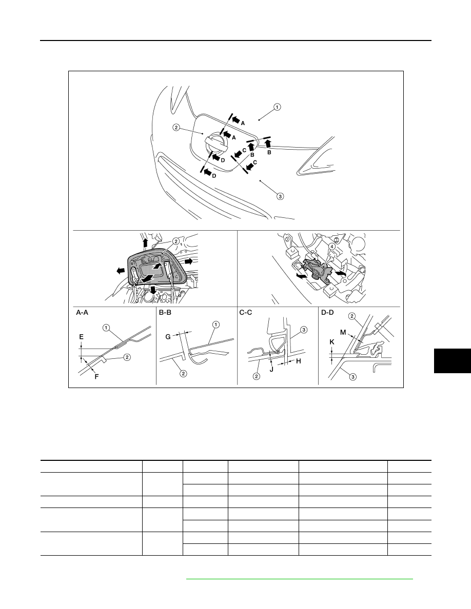
CHARGE PORT LID ASSEMBLY : Adjustment
INFOID:0000000010119855
Check the clearance and the surface height between charge port lid and each part by visual inspection and
tactile feel. If the clearance and the surface height are out of specification, adjust them according to the adjust-
ment procedure.
Unit: mm (in)
FITTING ADJUSTMENT PROCEDURE
1. Remove charge port cover. Refer to
DLK-160, "CHARGE PORT COVER : Removal and Installation"
1.
Hood assembly
2.
Charge port lid assembly
3.
Front bumper fascia
4.
Charge port lid lock
AWKIA2374ZZ
Portion
Section
Item
Measurement
Standard
Parallelism
Charge port lid – Hood
A – A
E
Clearance
5.0
± 2.7 (0.20 ± 0.11)
1.9 (0.07)
F
Surface height
1.0
± 2.0 (0.04 ± 0.08)
1.9 (0.07)
Charge port lid – Hood
B – B
G
Clearance
5.0
± 2.7 (0.20 ± 0.11)
2.9 (0.11)
Charge port lid – Front bumper
fascia
C – C
H
Clearance
2.6
± 1.2 (0.10 ± 0.05)
1.9 (0.07)
J
Surface height
1.5
± 1.5 (0.06 ± 0.06)
1.9 (0.07)
Charge port lid – Front bumper
fascia
D – D
K
Clearance
3.3
± 1.2 (0.13 ± 0.05)
1.9 (0.07)
M
Surface height
3.5
± 1.5 (0.14 ± 0.06)
1.9 (0.07)