Nissan Leaf. Manual - part 399
DOOR LOCK ACTUATOR
DLK-91
< DTC/CIRCUIT DIAGNOSIS >
C
D
E
F
G
H
I
J
L
M
A
B
DLK
N
O
P
3. Check continuity between BCM harness connector and ground.
Is the inspection result normal?
YES
>> GO TO 3.
NO
>> Repair or replace harness.
3.
CHECK BCM OUTPUT SIGNAL
1. Connect BCM connector.
2. Check voltage between BCM harness connector and ground.
Is the inspection result normal?
YES
>> Check for internal short of each door lock actuator.
NO
>> Replace BCM. Refer to
BCS-72, "Removal and Installation"
REAR LH
REAR LH : Component Function Check
INFOID:0000000010119770
1.
CHECK FUNCTION
1. Select “DOOR LOCK” of “BCM” using CONSULT.
2. Select “DOOR LOCK” in “Active Test”.
3. Check that the function operates normally according to the following conditions:
Is the inspection result normal?
YES
>> Door lock actuator is OK.
NO
>> Refer to
DLK-89, "DRIVER SIDE : Diagnosis Procedure"
REAR LH : Diagnosis Procedure
INFOID:0000000010119771
Regarding Wiring Diagram information, refer to
.
1.
CHECK DOOR LOCK ACTUATOR INPUT SIGNAL
1. Turn power switch OFF.
2. Disconnect rear door lock actuator LH connector.
3. Check voltage between rear door lock actuator LH harness connector and ground.
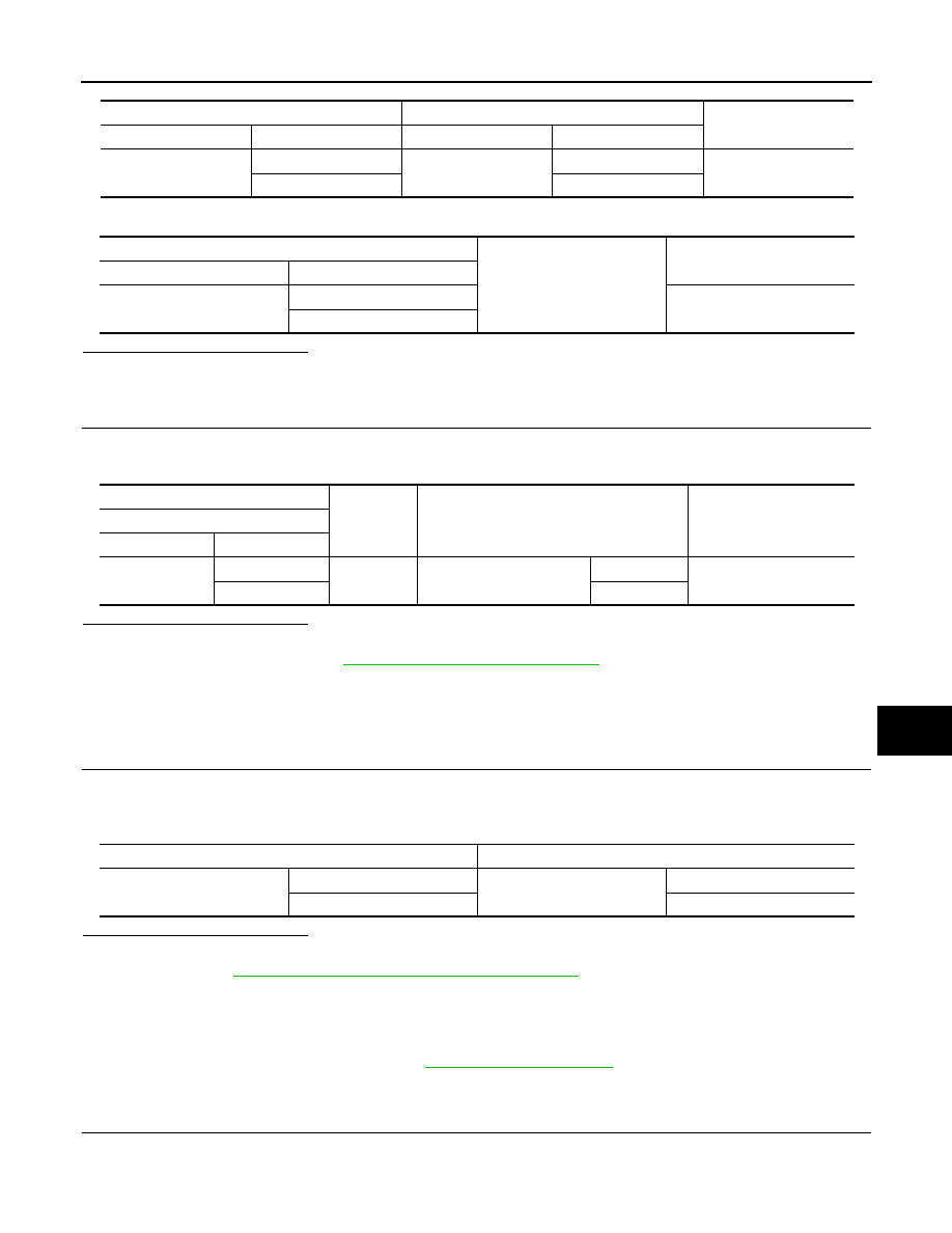
BCM
Front door lock actuator RH
Continuity
Connector
Terminal
Connector
Terminal
M25
59
D107
6
Yes
65
5
BCM
Ground
Continuity
Connector
Terminal
M25
59
No
65
(+)
(–)
Condition
Voltage
(Approx.)
BCM
Connector
Terminal
M25
59
Ground
Door lock and unlock switch
Unlock
Battery voltage
65
Lock
Monitor item
Status
DOOR LOCK
ALL LOCK
Door lock actuators
LOCK
ALL UNLK
UNLOCK