Nissan Leaf. Manual - part 343
BRC-162
< REMOVAL AND INSTALLATION >
[WITH VDC]
ABS ACTUATOR AND ELECTRIC UNIT (CONTROL UNIT)
ABS ACTUATOR AND ELECTRIC UNIT (CONTROL UNIT)
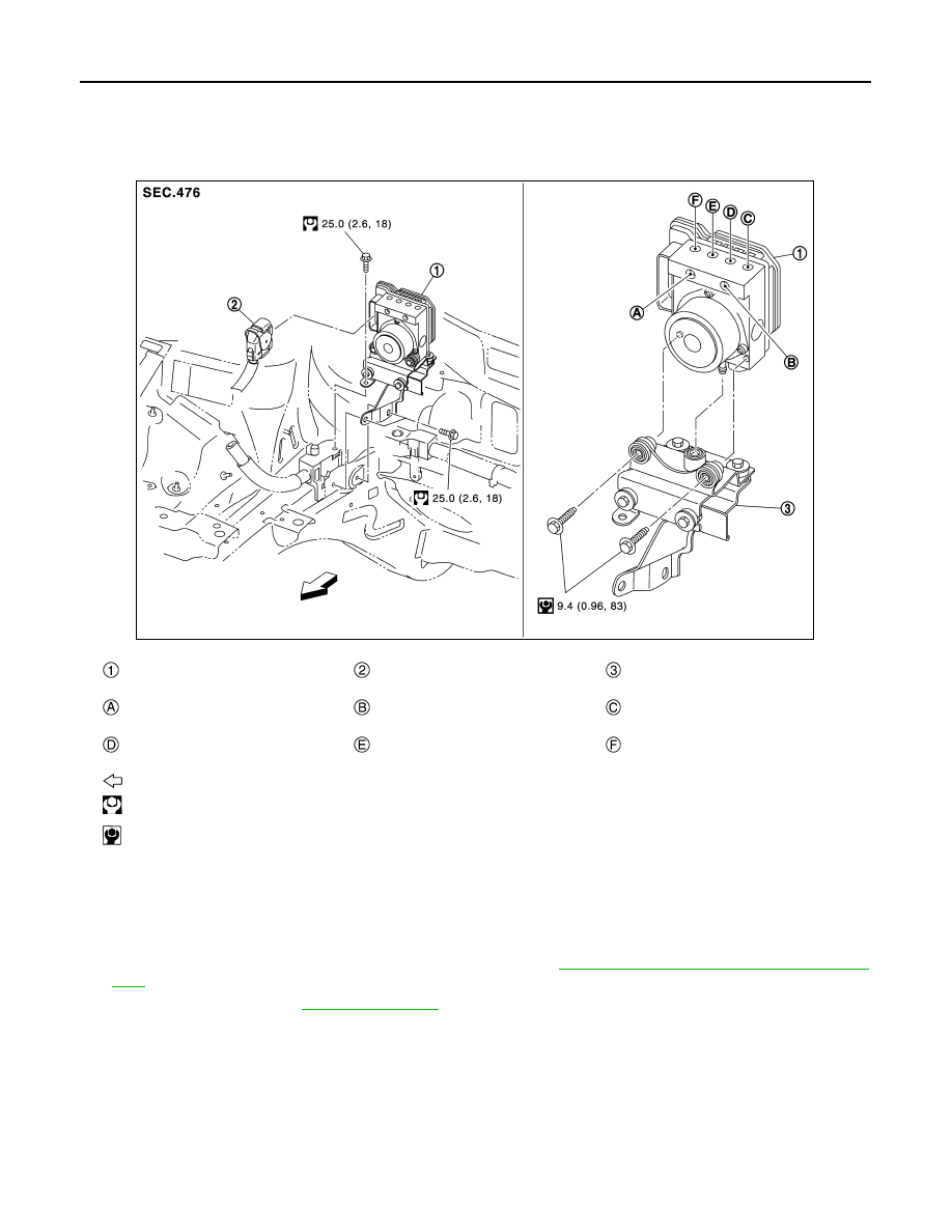
Exploded View
INFOID:0000000010120142
Removal and Installation
INFOID:0000000010120143
REMOVAL
1. Turn the power switch OFF.
2. Disconnect 12V battery cable from negative terminal. Refer to
BRC-5, "Precaution for Removing 12V Bat-
3. Drain brake fluid. Refer to
ABS actuator and electric unit (con-
trol unit)
ABS actuator and electric unit (con-
trol unit) harness connector
Bracket
To electrically-driven intelligent brake
unit secondary side
To electrically-driven intelligent brake
unit primary side
To front LH caliper
To rear RH caliper
To rear LH caliper
To front RH caliper
: Vehicle front
: N·m (kg-m, ft-lb)
: N·m (kg-m, in-lb)
JSFIA0698GB