Nissan Leaf. Manual - part 149
AV
U1A05 TCU
AV-587
< DTC/CIRCUIT DIAGNOSIS >
[TELEMATICS SYSTEM]
C
D
E
F
G
H
I
J
K
L
M
B
A
O
P
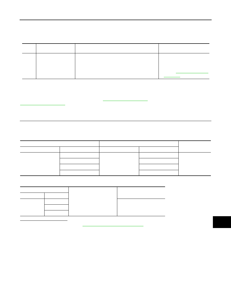
U1A05 TCU
DTC Logic
INFOID:0000000010122761
Diagnosis Procedure
INFOID:0000000010122762
Regarding Wiring Diagram information, refer to
(NAVIGATION WITHOUT BOSE) or
(NAVIGATION WITH BOSE).
1.
CHECK USB HARNESS CONTINUITY
1. Turn the power switch OFF.
2. Disconnect TCU and AV control unit connectors.
3. Check the continuity between TCU harness connector and AV control unit harness connector.
4. Check the continuity between TCU harness connector and ground.
Is the check result normal?
YES
>> Replace TCU. Refer to
AV-594, "Removal and Installation"
.
NO
>> Repair or replace the harness or connectors.
DTC
Display contents of CON-
SULT
DTC detection condition
Action to take
U1A05
USB COMM
[U1A05]
It is detected for malfunction of the USB communication
module (communication disabled) between TCU and AV
control unit.
• Check the USB harness con-
nection and erase DTC.
• Replace TCU if the malfunction
constantly occurs.
Refer to
.
TCU
AV control unit
Continuity
Connector
Terminal
Connector
Terminal
M68
47
M97 (without Bose)
M104 (with Bose)
62
Yes
48
61
55
70
56
69
TCU
Ground
Continuity
Connector
Terminal
M68
47
No
48
56