Nissan Leaf. Manual - part 1295


  Index      Nissan     Nissan Leaf (2011-2014 year) - Service and Repair Manual


Search            


Content   ..  1293  1294  1295  1296   ..


Nissan Leaf. Manual - part 1295


WW-8

< SYSTEM DESCRIPTION >

SYSTEM

SYSTEM

FRONT WIPER AND WASHER SYSTEM
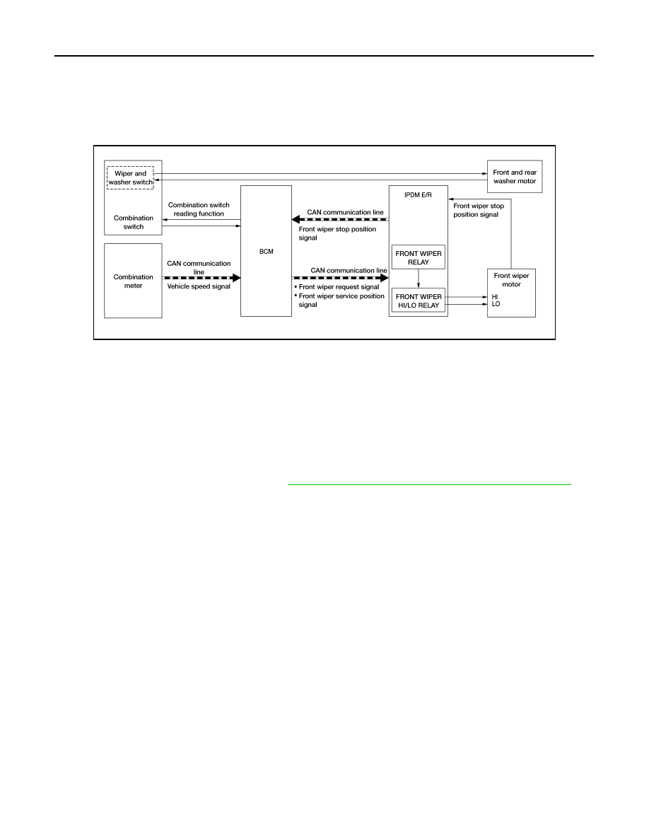
FRONT WIPER AND WASHER SYSTEM : System Description

INFOID:0000000010122199

SYSTEM DIAGRAM

OUTLINE

The front wiper is controlled by each function of BCM and IPDM E/R.

Control by BCM

• Combination switch reading function

• Front wiper control function

Control by IPDM E/R

• Front wiper control function

• Relay control function

Combination meter indicates low washer fluid warning judged by the signal from the washer fluid level switch.

For details of low washer fluid warning, refer to 

MWI-35, "INFORMATION DISPLAY : System Description"

.

FRONT WIPER BASIC OPERATION

• BCM detects the combination switch condition by the combination switch reading function.

• BCM transmits the front wiper request signal to IPDM E/R via CAN communication depending on each oper-

ating condition of the front wiper.

• IPDM E/R turns ON/OFF the integrated front wiper relay and the front wiper HI/LO relay according to the

front wiper request signal. IPDM E/R provides the power supply to operate the front wiper HI/LO operation.

FRONT WIPER LO OPERATION

• BCM transmits the front wiper request signal (LO) to IPDM E/R via CAN communication according to the

front wiper LO operating condition.

Front wiper LO operating condition

- Power switch ON

- Front wiper switch LO or front wiper switch MIST (while pressing)

• IPDM E/R turns ON the integrated front wiper relay according to the front wiper request signal (LO).

FRONT WIPER HI OPERATION

• BCM transmits the front wiper request signal (HI) to IPDM E/R via CAN communication according to the

front wiper HI operating condition.

Front wiper HI operating condition

- Power switch ON

- Front wiper switch HI

• IPDM E/R turns ON the integrated front wiper relay and the front wiper high relay according to the front wiper

request signal (HI).

FRONT WIPER INT OPERATION

AWLIA2357GB

SYSTEM

WW-9

< SYSTEM DESCRIPTION >

C

D

E

F

G

H

I

J

K

M

A

B

WW

N

O

P

• BCM transmits the front wiper request signal (INT) to IPDM E/R via CAN communication depending on the

front wiper INT operating condition and intermittent operation delay interval according to the wiper intermit-

tent dial position.

Front wiper INT operating condition

- Power switch ON

- Front wiper switch INT

• IPDM E/R turns ON the integrated front wiper relay so that the front wiper is operated only once according to

the front wiper request signal (INT).

• BCM detects stop position/except stop position of the front wiper motor according to the front wiper stop

position signal received from IPDM E/R via CAN communication.

• BCM transmits the front wiper request signal (INT) again after the intermittent operation delay interval.

NOTE:

Front wiper intermittent operation can be set to the operation with vehicle speed using CONSULT. Refer to

BCS-18, "WIPER : CONSULT Function - WIPER"

.

Front wiper intermittent operation with vehicle speed

• BCM calculates the intermittent operation delay interval from the following

- Vehicle speed signal 

- Wiper intermittent dial position

Unit: Second

*: When operation setting is not linked with vehicle speed. 

FRONT WIPER AUTO STOP OPERATION

• BCM stops transmitting the front wiper request signal when the front wiper switch is turned OFF.

• IPDM E/R detects the front wiper stop position signal from the front wiper motor and detects the front wiper

motor position (stop position/except stop position).

Wiper intermittent 

dial position

Intermittent 

operation 

interval

Intermittent operation delay Interval

Vehicle speed

0 – 5 km/h

(0 – 3.1 MPH)

5 – 65 km/h

(3.1 – 40.4 MPH)*

65 km/h (40.4 MPH) or more

1

Short

Long

1

0.4

0.24

2

2.5

1

0.6

3

5

2

1.2

4

7.5

3

1.8

5

12.5

5

3

6

25

10

6

7

40

16

9.6

JPLIA1256GB

WW-10

< SYSTEM DESCRIPTION >

SYSTEM

• When the front wiper request signal is stopped, IPDM E/R turns ON the front wiper relay until the front wiper

motor returns to the stop position.

NOTE:

• BCM stops the transmitting of the front wiper request signal when the power switch is OFF.

• IPDM E/R turns the front wiper relay OFF when the power switch is OFF.

FRONT WIPER OPERATION LINKED WITH WASHER

• BCM transmits the front wiper request signal (LO) to IPDM E/R via CAN communication according to the

washer linked operating condition of the front wiper.

• BCM transmits the front wiper request signal (LO) so that the front wiper operates approximately 2 times

when the front washer switch OFF is detected.

Washer linked operating condition of front wiper

- Turn power switch ON

- Front washer switch ON (0.4 second or more)

• IPDM E/R turns ON the integrated front wiper relay according to the front wiper request signal (LO).

• The washer motor is grounded through the combination switch with the front washer switch ON.

FRONT WIPER SERVICE POSITION OPERATION

• Front wiper operates in LO, stops, and then stays in lock back position when front washer switch is turned

ON while power switch is OFF.

• BCM transmits front wiper service position signal via CAN communication according to the front wiper ser-

vice position function operating conditions.

Operation conditions of front wiper service position function

- Turn power switch OFF (within 1 minutes)

- Front washer switch ON (0.4 second or more)

• Front wiper operates at LO and then stops when IPDM E/R detects front wiper service position signal.

• Front wiper service position function is cancelled when front wiper washer switch is turned ON again within 1

minute after turning power switch OFF. If 1 minute or more is passed after turning power switch OFF, front

wiper service position function is cancelled when power switch is turned ON again, and then front wiper

switch (INT, LO, HI, MIST or WASHER) is turned ON.

NOTE:

Front wiper does not operate even if front wiper switch (INT, LO, or HI) is ON when power switch is turned ON

while front wiper is stopped according to front wiper service position function.

WIPER LINKED AUTO LIGHTING FUNCTION (EXCEPT FOR CANADA)

When light switch is in the AUTO position, front wiper operates, and then headlamp illuminates. Refer to 

EXL-

15, "AUTO LIGHT SYSTEM (EXCEPT FOR CANADA) : System Description"

.

FRONT WIPER AND WASHER SYSTEM : Fail-safe

INFOID:0000000010122200

FAIL

−SAFE OPERATION

IPDM E/R performs the fail-safe function when the front wiper auto stop circuit is malfunctioning. Refer to

PCS-17, "Fail-Safe"

.

REAR WIPER AND WASHER SYSTEM

JPLIA0410GB

SYSTEM

WW-11

< SYSTEM DESCRIPTION >

C

D

E

F

G

H

I

J

K

M

A

B

WW

N

O

P

REAR WIPER AND WASHER SYSTEM : System Description

INFOID:0000000010122201

SYSTEM DIAGRAM

OUTLINE

The rear wiper is controlled by each function of BCM.

Control by BCM

• Combination switch reading function

• Rear wiper control function

REAR WIPER BASIC OPERATION

• BCM detects the combination switch condition by the combination switch reading function.

• BCM controls the rear wiper to start or stop.

REAR WIPER ON OPERATION

• BCM supplies power to the rear wiper motor according to the rear wiper ON operating condition.

Rear wiper ON operating condition

- Power switch ON

- Rear wiper switch ON

REAR WIPER INT OPERATION

• BCM supplies power to the rear wiper motor according to the INT operating condition.

Rear wiper INT operating condition

- Power switch ON

- Rear wiper switch INT

• BCM controls the rear wiper to operate once.

• BCM detects the rear wiper motor stopping position.

• BCM supplies power to the rear wiper motor after an intermittent from the stop of the rear wiper motor.

REAR WIPER AUTO STOP OPERATION

• BCM stops supplying power to the rear wiper motor when the rear wiper switch is turned OFF.

• BCM reads a rear wiper stop position signal from the rear wiper motor to detect a rear wiper motor position.

AWLIA2358GB

JPLIA1258GB


Content   ..  1293  1294  1295  1296   ..