Content .. 1291 1292 1293 1294 ..
Nissan Leaf. Manual - part 1293
SERVICE DATA AND SPECIFICATIONS (SDS)
WT-51
< SERVICE DATA AND SPECIFICATIONS (SDS)
C
D
F
G
H
I
J
K
L
M
A
B
WT
N
O
P
SERVICE DATA AND SPECIFICATIONS (SDS)
SERVICE DATA AND SPECIFICATIONS (SDS)
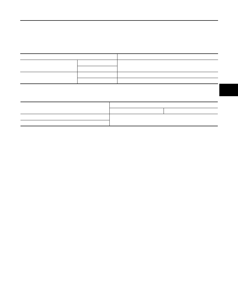
Road Wheel
INFOID:0000000010120220
Tire Air Pressure
INFOID:0000000010120221
Unit: kPa (kgf/cm
2
, psi)
Item
Limit
Runout
Axial runout
Less than 0.3 mm (0.012 in)
Radial runout
Allowable imbalance
Dynamic (At flange)
Less than 5 g (0.17 oz) (one side)
Static (At flange)
Less than 10 g (0.35 oz)
Item
Standard
Front
Rear
P205/55R16 89H
250 (2.55, 36)
P215/50R17 90V