Nissan Leaf. Manual - part 1228


  Index      Nissan     Nissan Leaf (2011-2014 year) - Service and Repair Manual


Search            


Content   ..  1226  1227  1228  1229   ..


Nissan Leaf. Manual - part 1228


B2840 PDM(POWER DELIVERY MODULE)

VC-79

< DTC/CIRCUIT DIAGNOSIS >

D

E

F

G

H

I

J

K

L

M

A

B

VC

N

O

P

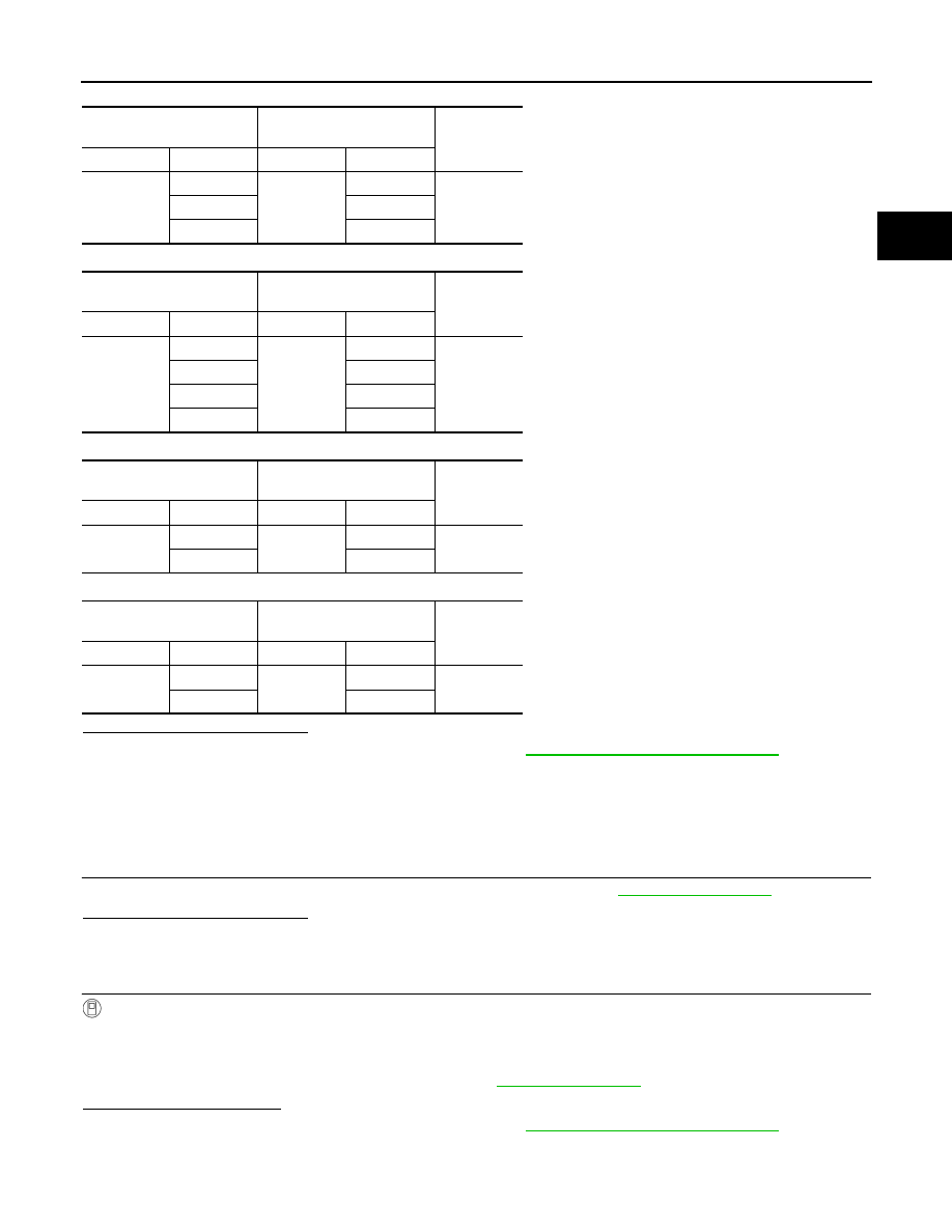
Electric compressor harness (with heat pump)

Electric compressor harness (without heat pump)

Quick charge port

Normal charge port

Is the inspection result normal?

YES

>> Replace PDM (Power Delivery Module). Refer to 

VC-112, "Removal and Installation"

.

NO

>> Repair or replace error-detected parts.

TYPE C
TYPE C : Diagnosis Procedure

INFOID:0000000010121263

1.

CHECK HIGH VOLTAGE COOLING SYSTEM

Inspect coolant level and leakage of high voltage cooling system. Refer to 

HCO-11, "Inspection"

.

Is the inspection result normal?

YES

>> GO TO 2.

NO

>> Repair or replace error-detected parts.

2.

PERFORM DTC CONFIRMATION PROCEDURE AGAIN

With CONSULT

1. Turn power switch ON.

2. Erase DTC.

3. Turn power switch OFF.

4. Perform DTC confirmation procedure again. Refer to 

VC-76, "DTC Logic"

.

Is the DTC detected again?

YES

>> Replace PDM (Power Delivery Module). Refer to 

VC-112, "Removal and Installation"

.

NO

>> INSPECTION END

PDM

(Power Delivery Module)

Electric compressor

Continuity

Connector

Terminal

Connector

Terminal

H6

41

H25

2

Existed

42

1

43

3

PDM

(Power Delivery Module)

Electric compressor

Continuity

Connector

Terminal

Connector

Terminal

H7

41

H1

1

Existed

42

2

43

3

44

4

PDM

(Power Delivery Module)

Quick charge port

Continuity

Connector

Terminal

Connector

Terminal

H8

45

H10

11

Existed

46

12

PDM

(Power Delivery Module)

Normal charge port

Continuity

Connector

Terminal

Connector

Terminal

H9

47

H11

3

Existed

48

4

VC-80

< DTC/CIRCUIT DIAGNOSIS >

B2850 PDM(POWER DELIVERY MODULE)

B2850 PDM(POWER DELIVERY MODULE)

Description

INFOID:0000000010121264

Two temperature sensors are integrated in the PDM (Power Delivery Module), and monitor the charging circuit

temperature and control circuit board temperature.

The PDM (Power Delivery Module) also detects sensor accuracy malfunctions by comparing the signals from

each sensor.

DTC Logic

INFOID:0000000010121265

DTC DETECTION LOGIC

DTC CONFIRMATION PROCEDURE

1.

PERFORM DTC CONFIRMATION PROCEDURE

With CONSULT

1. Perform normal charging for 30 seconds or more.

2. Turn power switch ON.

3. Check “Self-diagnosis result” of “CHARGER/PD MODULE”.
Is DTC detected?

YES

>> Proceed to 

VC-80, "Diagnosis Procedure"

.

NO

>> INSPECTION END

Diagnosis Procedure

INFOID:0000000010121266

1.

PERFORM DTC CONFIRMATION PROCEDURE AGAIN

With CONSULT

1. Turn power switch ON.

2. Erase DTC.

3. Turn power switch OFF.

4. Perform DTC confirmation procedure again. Refer to 

VC-80, "DTC Logic"

.

Is the DTC detected again?

YES

>> Replace PDM (Power Delivery Module). Refer to 

VC-112, "Removal and Installation"

.

NO

>> INSPECTION END

DTC

CONSULT display

(Malfunction type)

DTC detection condition

Possible causes

B2850

PD MODULE TEMP SEN
(Signal stuck low)

During normal charging, the signal voltage of the temperature 
sensor inside the PDM (Power Delivery Module) is excessively 
low continuously for 30 seconds or more.

PDM (Power Delivery Mod-
ule)

B2880 F/S CHG RELAY

VC-81

< DTC/CIRCUIT DIAGNOSIS >

D

E

F

G

H

I

J

K

L

M

A

B

VC

N

O

P

B2880 F/S CHG RELAY

DTC Logic

INFOID:0000000010121267

DTC DETECTION LOGIC

DTC CONFIRMATION PROCEDURE

1.

PERFORM DTC CONFIRMATION PROCEDURE

With CONSULT

1. Perform quick charging for 15 seconds or more.

2. Turn power switch ON.

3. Check self-diagnosis results.
Is DTC detected?

YES (TYPE A)>>Proceed to 

VC-81, "TYPE A : Diagnosis Procedure"

.

YES (TYPE B)>>Proceed to 

VC-83, "TYPE B : Diagnosis Procedure"

.

NO

>> INSPECTION END

TYPE A
TYPE A : Diagnosis Procedure

INFOID:0000000010121268

1.

CHECK QUICK CHARGE RELAY OPERATION

With CONSULT

1. Turn power switch ON.

2. Select “Q/CHG RELAY +” in “ACTIVE TEST” mode of “CHARGER/PD MODULE” using CONSULT. 

3. Switch the quick charge relay between ON and OFF to check operating noise.

NOTE:

If operating noise is hard to hear, use a sound scope to check noise.

4. Check “Q/CHG RELAY 

−” in same manner.

Can operating sound be heard?

YES

>> GO TO 2.

NO

>> GO TO 3.

2.

PERFORM DTC CONFIRMATION PROCEDURE AGAIN

With CONSULT

1. Erase DTC.

2. Turn power switch OFF.

3. Perform DTC confirmation procedure again. Refer to 

VC-81, "DTC Logic"

.

Is the DTC detected again?

YES

>> Replace PDM (Power delivery module). Refer to  

VC-112, "Removal and Installation"

.

NO

>> INSPECTION END

3.

CHECK F/S CHG RELAY OPERATION

With CONSULT

1. Select “F/S CHG RLY” in “ACTIVE TEST” mode of “EV/HEV” using CONSULT.

2. Switch the F/S CHG relay between ON and OFF to check operating noise of the F/S CHG relay.

DTC

CONSULT display

(Malfunction type)

DTC detection condition

Possible causes

B2880

A

F/S CHARGE RELAY
(Signal stuck low)

During quick charging, the voltage of the 
quick charge relay control circuit is less than 
approximately 4.21 V continuously for 3 sec-
onds.

• Harness and connector
• Quick charge relay
• PDM (Power Delivery Module)
• F/S CHG relay
• F/S  relay

B

F/S CHARGE RELAY
(Signal stuck high)

During quick charging, the voltage of the 
quick charge relay control circuit is 4.69 V or 
more continuously for 3 seconds.

• Harness and connector
• PDM (Power Delivery Module)
• F/S CHG relay
• F/S  relay

VC-82

< DTC/CIRCUIT DIAGNOSIS >

B2880 F/S CHG RELAY

Can operating sound be heard?

YES

>> GO TO 4.

NO

>> Perform the trouble diagnosis for F/S CHG relay system. Refer to 

EVC-373, "Diagnosis Proce-

dure"

.

4.

CHECK F/S CHG RELAY SIGNAL

With CONSULT

1. Turn power switch OFF.
2. Disconnect PDM (Power Delivery Module) harness connector .

NOTE:

Loosen the PDM (Power Delivery Module) harness connector by

rotating it counterclockwise and remove it.

3. Turn power switch ON.

4. Select “F/S CHG RLY” in “ACTIVE TEST” mode of “EV/HEV”

using CONSULT.

5. Turn ON the F/S CHG relay.

6. Check the voltage between PDM (Power Delivery Module) har-

ness connector and ground.

Is the inspection result normal?

YES

>> Replace PDM (Power Delivery Module). Refer to 

VC-112, "Removal and Installation"

.

NO

>> GO TO 5

5.

CHECK F/S CHG RELAY SIGNAL CIRCUIT

1. Turn power switch OFF.

2. Remove F/S CHG relay.

3. Check the continuity between PDM (Power Delivery Module) harness connector and F/S CHG relay har-

ness connector.

Is the inspection result normal?

YES

>> GO TO 6.

NO

>> Repair or replace error-detected parts.

6.

CHECK 12V BATTERY POWER SUPPLY (1)

Check the voltage between F/S CHG relay harness connector and ground.

Is the inspection result normal?

: Vehicle front

+

Voltage

PDM

(Power Delivery Module)

Connector

Terminal

F23

9

Ground

12V battery volt-

age

JSCIA0693ZZ

PDM

(Power Delivery Module)

F/S CHG relay

Continuity

Connector

Terminal

Connector

Terminal

F23

9

E64

5

Existed

+

Voltage

F/S CHG relay

Connector

Terminal

E64

3

Ground

12V battery volt-

age


Content   ..  1226  1227  1228  1229   ..