Nissan Leaf. Manual - part 1229


  Index      Nissan     Nissan Leaf (2011-2014 year) - Service and Repair Manual


Search            


Content   ..  1227  1228  1229  1230   ..


Nissan Leaf. Manual - part 1229


B2880 F/S CHG RELAY

VC-83

< DTC/CIRCUIT DIAGNOSIS >

D

E

F

G

H

I

J

K

L

M

A

B

VC

N

O

P

YES

>> Replace F/S CHG relay.

NO

>> GO TO 7.

7.

CHECK FUSE

Check that the following fuse is not fusing.

Is the fuse fusing?

YES

>> Replace the fuse after repairing the applicable circuit.

NO

>> GO TO 8.

8.

CHECK 12V BATTERY POWER SUPPLY (2)

1. Pull out #33 fuse.

2. Check the voltage between fuse terminal and ground.

Is the inspection result normal?

YES

>> GO TO 9.

NO

>> Perform the trouble diagnosis for 12V battery power supply circuit.

9.

CHECK 12V BATTERY POWER SUPPLY CIRCUIT

Check the continuity between F/S CHG relay harness connector and fuse terminal.

Is the inspection result normal?

YES

>> Check the intermittent incident. Refer to 

GI-53, "Intermittent Incident"

.

NO

>> Repair or replace error-detected parts

TYPE B
TYPE B : Diagnosis Procedure

INFOID:0000000010121269

1.

CHECK F/S CHG RELAY SIGNAL CIRCUIT

1. Turn power switch OFF.
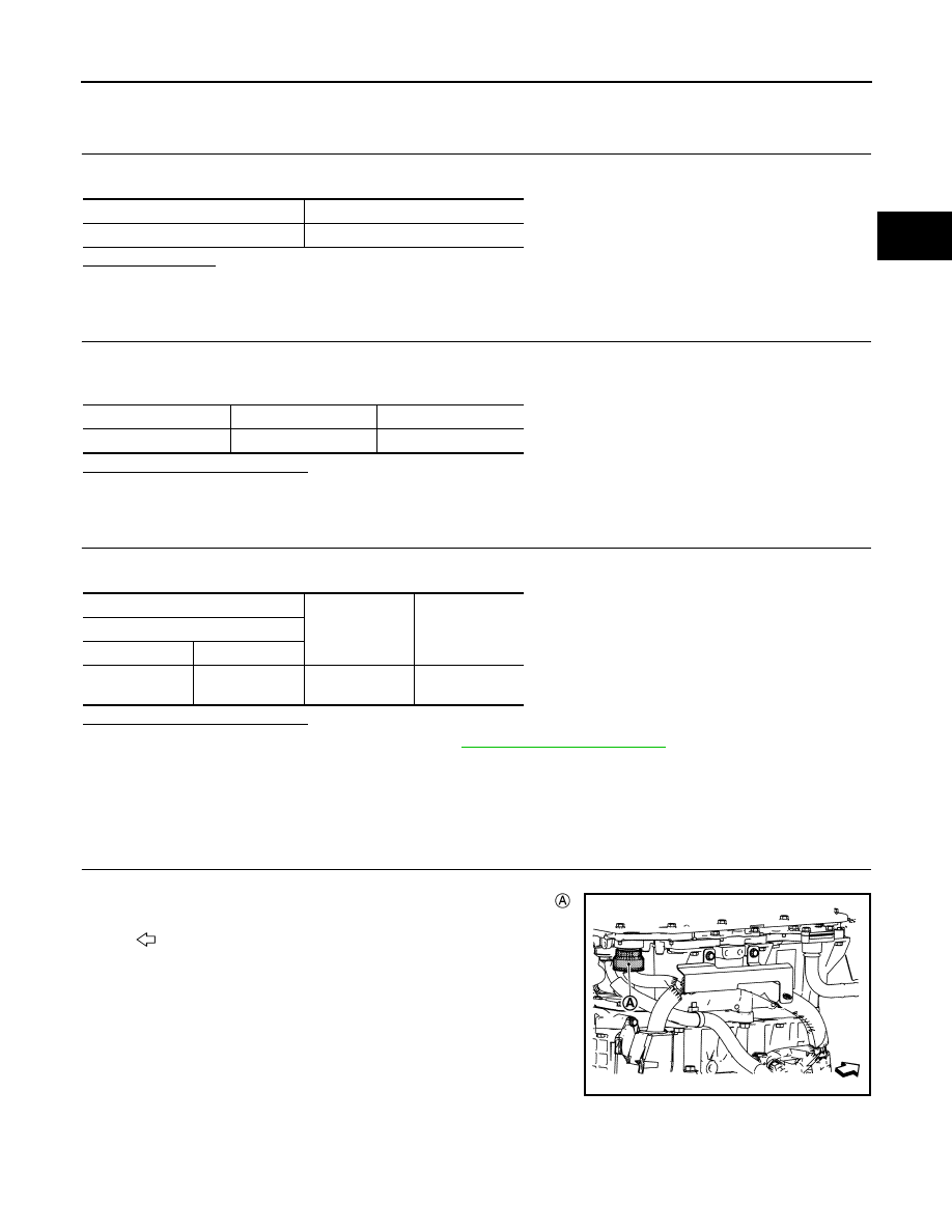
2. Disconnect PDM (Power Delivery Module) harness connector .

NOTE:

Loosen the PDM (Power Delivery Module) harness connector by

rotating it counterclockwise and remove it.

3. Turn power switch ON.

4. Check the voltage between PDM (Power Delivery Module) har-

ness connector and ground.

Fuse No.

Capacity

#33

10 A

+

Voltage

#33 fuse terminal

Ground

12V battery voltage

+

Continuity

F/S CHG relay

Connector

Terminal

E64

3

#33 fuse termi-

nal

Existed

: Vehicle front

JSCIA0693ZZ

VC-84

< DTC/CIRCUIT DIAGNOSIS >

B2880 F/S CHG RELAY

Is the inspection result normal?

YES

>> GO TO 3.

NO

>> GO TO 2.

2.

CHECK F/S CHG RELAY POWER SUPPLY

1. Turn power switch OFF.

2. Remove F/S CHG relay.

3. Turn power switch ON.

4. Check the voltage between PDM (Power Delivery Module) harness connector and ground.

Is the inspection result normal?

YES

>> Perform the trouble diagnosis for F/S CHG relay system. Refer to 

EVC-373, "Diagnosis Proce-

dure"

.

NO

>> There may be a short circuit in the location between power and an area between F/S CHG relay

harness connector and PDM (Power Delivery Module) harness connector. Check the harness for

short circuit.

3.

CHECK INTERMITTENT INCIDENT

Check the intermittent incident. Refer to 

GI-53, "Intermittent Incident"

.

Is the inspection result normal?

YES

>> Replace PDM (Power Delivery Module). Refer to 

VC-112, "Removal and Installation"

.

NO

>> Repair or replace error-detected parts.

+

Voltage

(Approx.)

PDM

(Power Delivery Module)

Connector

Terminal

F23

9

Ground

0 V

+

Voltage

(Approx.)

PDM

(Power Delivery Module)

Connector

Terminal

F23

9

Ground

0 V

B2890 DC/DC CONVERTER

VC-85

< DTC/CIRCUIT DIAGNOSIS >

D

E

F

G

H

I

J

K

L

M

A

B

VC

N

O

P

B2890 DC/DC CONVERTER

DTC Logic

INFOID:0000000010121270

DTC DETECTION LOGIC

DTC CONFIRMATION PROCEDURE

1.

PERFORM DTC CONFIRMATION PROCEDURE

With CONSULT

1. Set the vehicle to READY and wait 120 seconds or more.

2. Check “Self-diagnosis result” of “CHARGER/PD MODULE”.
Is DTC detected?

YES (TYPE A)>>Proceed to 

VC-85, "TYPE A AND E : Diagnosis Procedure"

.

YES (TYPE B)>>Proceed to 

VC-86, "TYPE B : Diagnosis Procedure"

.

YES (TYPE C)>>Proceed to 

VC-87, "TYPE C : Diagnosis Procedure"

.

YES (TYPE D)>>Proceed to 

VC-87, "TYPE D : Diagnosis Procedure"

.

YES (TYPE E)>>Proceed to 

VC-85, "TYPE A AND E : Diagnosis Procedure"

.

NO

>> INSPECTION END

TYPE A AND E
TYPE A AND E : Diagnosis Procedure

INFOID:0000000010121271

1.

CHECK 12V BATTERY

Check the 12V battery. Refer to 

PG-83, "How to Handle 12V Battery"

.

Is the inspection result normal?

YES

>> GO TO 2.

NO

>> Replace 12V battery. Refer to 

PG-89, "Removal and Installation"

.

2.

CHECK 12V BATTERY CABLE ON PDM (POWER DELIVERY MODULE) SIDE (1)

1. Turn power switch OFF.

DTC

CONSULT display

(Malfunction type)

DTC detection condition

Possible causes

B2890

A

DC/DC CONVERTER
(Circuit voltage below thresh-
old)

During quick or normal charging, or during driving, the 12 
V DC/DC converter inside the PDM (Power Delivery Mod-
ule) outputs an excessively low voltage continuously for 3 
seconds or more, or output, an excessively low voltage for 
less than 3 seconds, 20 times.

• 12V battery
• Harness and con-

nector

• PDM (Power Deliv-

ery Module)

B

DC/DC CONVERTER
(Electrical malfunction)

During quick or normal charging, or during driving, an irreg-
ular voltage is input into the 12 V DC/DC converter inside 
the PDM (Power Delivery Module) continuously for 3 sec-
onds or more, or is input continuously for less than 3 sec-
onds, 20 times.

• Harness and con-

nector

• PDM (Power Deliv-

ery Module)

C

DC/DC CONVERTER
(Component internal malfunc-
tion)

An I2C communication malfunction (12 V DC/DC control 
section) occurs.

PDM (Power Deliv-
ery Module)

D

DC/DC CONVERTER
(Component or system over 
temperature)

During quick or normal charging, or during driving, the tem-
perature of the 12 V DC/DC converter inside the PDM 
(Power Delivery Module) is excessively high continuously 
for 3 seconds or more, or is excessively high continuously 
for less than 3 seconds, 20 times.

• High voltage cool-

ing system

- Cooling fan (VCM)
- Engine coolant lev-

el

• PDM (Power Deliv-

ery Module)

E

DC/DC CONVERTER
(Circuit volt above threshold)

When the output voltage of the 12 V DC/DC converter 
mounted inside PDM (Power Delivery Module) is extremely 
high during quick/normal charge or driving.

• 12V battery
• Harness and con-

nector

• PDM (Power Deliv-

ery Module)

VC-86

< DTC/CIRCUIT DIAGNOSIS >

B2890 DC/DC CONVERTER

2. Check the installation of 12V battery negative cable  and 12V

battery positive cable . [PDM (Power Delivery Module) side.]

Is the inspection result normal?

YES

>> GO TO 3.

NO

>> Repair or replace 12V battery negative cable or positive cable on PDM (Power Delivery Module)

side connection.

3.

CHECK 12V BATTERY CABLE ON PDM (POWER DELIVERY MODULE) SIDE (2)

1. Disconnect 12V battery negative and positive terminal. Refer to 

VC-5, "Precautions for Removing Battery

Terminal"

.

2. Remove 12V battery negative and positive cable on PDM (Power Delivery Module) side.

3. Check the continuity between 12V battery negative cable terminal on PDM (Power Delivery Module) side

and 12V battery negative terminal, between 12V battery positive cable terminal on PDM (Power Delivery

Module) side and 12V battery positive terminal.

Is the inspection result normal?

YES

>> Replace PDM (Power Delivery Module). Refer to 

VC-112, "Removal and Installation"

.

NO

>> Repair or replace error-detected parts.

TYPE B
TYPE B : Diagnosis Procedure

INFOID:0000000010121272

DANGER:

Since hybrid vehicles and electric vehicles contain a high voltage battery, there is the risk of

electric shock, electric leakage, or similar accidents if the high voltage component and vehicle are

handled incorrectly. Be sure to follow the correct work procedures when performing inspection and

maintenance.

WARNING:

• Be sure to remove the service plug in order to disconnect the high voltage circuits before perform-

ing inspection or maintenance of high voltage system harnesses and parts.

• The removed service plug must always be carried in a pocket of the responsible worker or placed in

the tool box during the procedure to prevent the plug from being connected by mistake.

• Be sure to wear insulating protective equipment consisting of glove, shoes, face shield and glasses

before beginning work on the high voltage system.

• Never allow workers other than the responsible person to touch the vehicle containing high voltage

parts. To keep others from touching the high voltage parts, these parts must be covered with an insu-

lating sheet except when using them.

• Refer to 

VC-6, "High Voltage Precautions"

.

ALCIA0137ZZ

+

Continuity

PDM (Power Delivery Mod-

ule) side

12V battery side

Connector

Terminal

F32

51

12V battery negative ter-
minal

Existed

E201

37

12V battery positive ter-
minal


Content   ..  1227  1228  1229  1230   ..