Content .. 1224 1225 1226 1227 ..
Nissan Leaf. Manual - part 1226
B2814 QUICK CHARGE RELAY
VC-71
< DTC/CIRCUIT DIAGNOSIS >
D
E
F
G
H
I
J
K
L
M
A
B
VC
N
O
P
B2814 QUICK CHARGE RELAY
DTC Logic
INFOID:0000000010121254
DTC DETECTION LOGIC
DTC CONFIRMATION PROCEDURE
1.
PERFORM DTC CONFIRMATION PROCEDURE
With CONSULT
1. Perform quick charging for 10 seconds or more.
2. Turn power switch ON.
3. Check “Self-diagnosis result” of “CHARGER/PD MODULE”.
Is DTC detected?
YES
>> Proceed to
NO
>> INSPECTION END
Diagnosis Procedure
INFOID:0000000010121255
1.
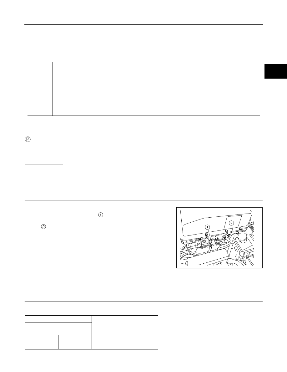
CHECK 12V BATTERY NEGATIVE CABLE ON PDM (POWER DELIVERY MODULE) SIDE (1)
1. Turn power switch OFF.
2. Check the installation of 12V battery negative cable on PDM
(Power Delivery Module) side .
Is the inspection result normal?
YES
>> GO TO 2.
NO
>> Repair or replace 12V battery negative cable on PDM (Power Delivery Module) side connection.
2.
CHECK 12V BATTERY NEGATIVE CABLE ON PDM (POWER DELIVERY MODULE) SIDE (2)
Check the continuity between 12V battery negative cable on PDM (Power Delivery Module) side and ground.
Is the inspection result normal?
DTC
CONSULT display
(Malfunction type)
DTC detection condition
Possible causes
B2814
QUICK CHARGE RELAY
(Signal stuck high)
• When the quick charge relay is ON, the termi-
nal voltage in the quick charge relay drive cir-
cuit is 4.69 V or more continually for 3 seconds
or more.
• When the quick charge relay is ON, the high
voltage circuit voltage that is input from the
quick charge sensor is 60 V or more continu-
ally for 1 second or more.
• Harness and connector
[PDM (Power Delivery Module)
ground circuit is open.]
• PDM (Power Delivery Module)
: 12V battery positive cable
ALCIA0137ZZ
+
−
Continuity
PDM
(Power Delivery Module)
Connector
Terminal
F32
51
Ground
Existed