Nissan Leaf. Manual - part 1223


  Index      Nissan     Nissan Leaf (2011-2014 year) - Service and Repair Manual


Search            


Content   ..  1221  1222  1223  1224   ..


Nissan Leaf. Manual - part 1223


U1008, U100B QUICK CHARGER COMMUNICATION

VC-59

< DTC/CIRCUIT DIAGNOSIS >

D

E

F

G

H

I

J

K

L

M

A

B

VC

N

O

P

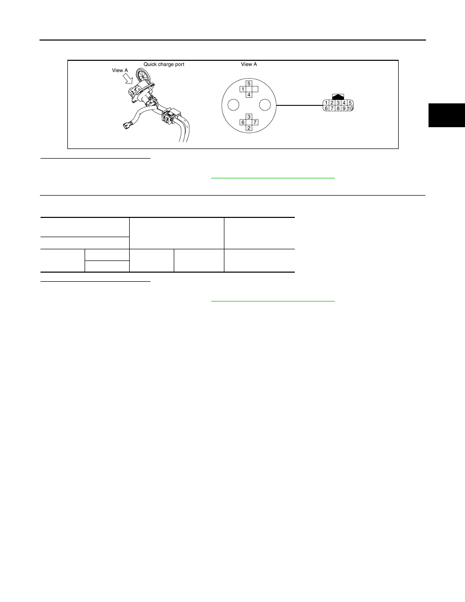
2. Check the continuity between quick charge port terminals and quick charge port side harness connector

of same terminals.

Is the inspection result normal?

YES

>> GO TO 2.

NO

>> Replace quick charge port. Refer to 

VC-128, "Removal and Installation"

.

2.

CHECK QUICK CHARGE PORT TEMPERATURE SENSOR

Check the resistance between quick charge port side harness connector terminals.

Is the inspection result normal?

YES

>> INSPECTION END

NO

>> Replace quick charge port. Refer to 

VC-128, "Removal and Installation"

.

JSCIA0660GB

Quick charge side harness 

connector

Condition

Resistance (k

Ω)

Terminal

5

9

Temperature 
[

°C (°F)]

-40 – 50 
(

−40 – 122)

− 170

10

VC-60

< DTC/CIRCUIT DIAGNOSIS >

U100A CAN COMMUNICATION

U100A CAN COMMUNICATION

Description

INFOID:0000000010121239

CAN (Controller Area Network) is a serial communication line for real time application. It is an on-vehicle mul-

tiplex communication line with high data communication speed and excellent error detection ability. Many elec-

tronic control units are equipped onto a vehicle, and each control unit shares information and links with other

control units during operation (not independent). In CAN communication, control units are connected with 2

communication lines (CAN H line, CAN L line) allowing a high rate of information transmission with less wiring.

Each control unit transmits/receives data but selectively reads required data only.

DTC Logic

INFOID:0000000010121240

DTC DETECTION LOGIC

DTC CONFIRMATION PROCEDURE

1.

PERFORM DTC CONFIRMATION PROCEDURE

With CONSULT

1. Turn power switch ON and wait for 5 seconds or more.

2. Check “Self-diagnosis result” of “CHARGER/PD MODULE”.
Is DTC detected?

YES

>> Proceed to 

VC-60, "Diagnosis Procedure"

.

NO

>> INSPECTION END

Diagnosis Procedure

INFOID:0000000010121241

Perform the trouble diagnosis for CAN communication system. Refer to 

LAN-17, "Trouble Diagnosis Flow

Chart"

.

DTC

CONSULT display

(Malfunction type)

DTC detection condition

Possible causes

U100A

CAN COMM ERROR
(Missing message)

The PDM (Power Delivery Module) is unable to send or re-
ceive EV system CAN communication continually for 2 
seconds or more.

Harness and connector
(EV system CAN communica-
tion line circuit is open or 
shorted.)

U1010 CONTROL MODULE (CAN)

VC-61

< DTC/CIRCUIT DIAGNOSIS >

D

E

F

G

H

I

J

K

L

M

A

B

VC

N

O

P

U1010 CONTROL MODULE (CAN)

DTC Logic

INFOID:0000000010121242

DTC DETECTION LOGIC

DTC CONFIRMATION PROCEDURE

1.

PERFORM DTC CONFIRMATION PROCEDURE

With CONSULT

1. Turn power switch ON and wait for 5 seconds or more.

2. Check “Self-diagnosis result” of “CHARGER/PD MODULE”.
Is DTC detected?

YES

>> Proceed to 

VC-61, "Diagnosis Procedure"

.

NO

>> INSPECTION END

Diagnosis Procedure

INFOID:0000000010121243

1.

PERFORM DTC CONFIRMATION PROCEDURE AGAIN

With CONSULT

1. Turn power switch ON.

2. Erase DTC.

3. Perform DTC confirmation procedure again. Refer to 

VC-61, "DTC Logic"

.

Is the DTC detected again?

YES

>> Replace PDM (Power Delivery Module). Refer to 

VC-60, "Diagnosis Procedure"

NO

>> INSPECTION END

DTC

CONSULT display

(Malfunction type)

DTC detection condition

Possible causes

U1010

CONTROL UNIT (CAN)
(Internal electric malfnctn)

In a self-test of CAN control unit, when PDM (Power Deliv-
ery Module) is under conditions that a write value and a 
read value do not match one time or more out of two at-
tempts, and after that, they never match even after 100 at-
tempts.

PDM (Power Delivery Module)

CONTROL UNIT (CAN)
(Electrical malfunction)

VC-62

< DTC/CIRCUIT DIAGNOSIS >

B2801 QUICK CHARGE CONNECTOR

B2801 QUICK CHARGE CONNECTOR

DTC Logic

INFOID:0000000010121244

DTC DETECTION LOGIC

CAUTION:

This DTC may be detected when there is a quick charger malfunction. Therefore if this DTC is

detected, check that there are no malfunctions in the quick charger.

DTC CONFIRMATION PROCEDURE

1.

PERFORM DTC CONFIRMATION PROCEDURE

With CONSULT

1. Turn power switch OFF.

2. Connect the quick charger connector to the quick charge port.

3. Turn ON the quick charger start switch and wait for 1 minute or more.

4. Turn power switch ON.

5. Check “Self-diagnosis result” of “CHARGER/PD MODULE”.
Is DTC detected?

YES (TYPE A)>>Proceed to 

VC-62, "TYPE A : Diagnosis Procedure"

.

YES (TYPE B)>>Proceed to 

VC-64, "TYPE B : Diagnosis Procedure"

.

NO

>> INSPECTION END

TYPE A
TYPE A : Diagnosis Procedure

INFOID:0000000010121245

1.

PERFORM DTC CONFIRMATION PROCEDURE AGAIN

With CONSULT

1. Turn power switch ON.

2. Erase DTC.

3. Turn power switch OFF.

4. Perform DTC confirmation procedure again by using a quick charger other than the one is used for the

previous DTC confirmation procedure. Refer to 

VC-62, "DTC Logic"

Is DTC detected?

YES

>> GO TO 2.

NO

>> INSPECTION END (Quick charger malfunction).

2.

CHECK QUICK CHARGE PORT CONDITION

Check for any adhering foreign substances, cracking or damage on the quick charge port. Refer to 

VC-52,

"Inspection"

.

Is the inspection result normal?

YES

>> GO TO 3.

NO

>> Clean or replace the quick charge port. Refer to 

VC-128, "Removal and Installation"

.

DTC

CONSULT display

(Malfunction type)

DTC detection condition

Possible causes

B2801

A

Q/CHG ACTIVATION SIG 
ERROR
(Signal invalid)

Quick charger connector disconnection is detect-
ed while receiving the quick charge start/stop 1 
signal that is transmitted from the quick charger. 

• Harness and connector

(Quick charge port circuit is 
open or shorted.)

• Quick charger
• Quick charge port
• PDM (Power Delivery Mod-

ule)

B

Q/CHG ACTIVATION SIG 
ERROR
(Signal stuck high)

The connector connection confirmation signal is 
detected continuously for 3 seconds or more be-
cause the signal line cut-off circuit is stuck ON 
during quick charging.

PDM (Power Delivery Module)


Content   ..  1221  1222  1223  1224   ..