Nissan Leaf. Manual - part 1221


  Index      Nissan     Nissan Leaf (2011-2014 year) - Service and Repair Manual


Search            


Content   ..  1219  1220  1221  1222   ..


Nissan Leaf. Manual - part 1221


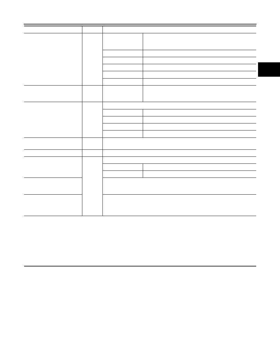
DIAGNOSIS AND REPAIR WORK FLOW

VC-51

< BASIC INSPECTION >

D

E

F

G

H

I

J

K

L

M

A

B

VC

N

O

P

Quick charger

Q

Quick charger maker

†

 Not applicable

†

 Applicable

(

)

Location

Model number

Serial number

Setting

Others

EVSE

N

Manufacturer

†

 Genuine

†

 Other

(

)

Wall outlet

N

†

 Not applicable † Applicable

Location

Voltage

V

Breaker

 A

Other information

Li-ion battery remaining energy

Q/N/O

†

 Not applicable † Applicable

(

)

Shift position/operation

R

†

 P † R † N † D † ECO † When operating (

)

Weather condition

R/Q/N/O

†

 Not applicable † Applicable

Weather

Temperature

°C (or °F)

Occurrence frequency

†

 All the time † Once † Sometimes (        times in the past)

†

 Others

(

)

Timing of recovery from mal-
function

†

 POWER OFF † Removal of 12V battery terminal † Shift lever operation

†

 During driving † READY

†

 Others

(

)

Question

Group

Information from the customer

VC-52

< PERIODIC MAINTENANCE >

CHARGE PORT

PERIODIC MAINTENANCE

CHARGE PORT

Inspection

INFOID:0000000010121230

INSPECTION PROCEDURES

Quick Charge Port

1. Perform the following visual inspections.

• Dust and foreign matter in the quick charge port and normal charge port

• Damage in the quick charge port and normal charge port

• Malfunction in opening/closing the charge port caps and looseness when closed and locked.
• Cracks in the packing   of quick charge port

• Check that the quick charge port terminals   are not welded.

CAUTION:

If they are welded, inspect the quick charge gun used for

the last charge, and replace the quick charge port. For

replacement of the quick charge port, refer to 

VC-128,

"Removal and Installation"

.

• Check that there is no irregular wear of the quick charge port lock  .

• If the port is damaged, for example if the metal plate   on the inside is lost, replace the quick charge

port. For replacement of the quick charge port, refer to 

VC-128, "Removal and Installation"

.

JSCIA0211ZZ

JPCIA0367ZZ

JPCIA0368ZZ

CHARGE PORT

VC-53

< PERIODIC MAINTENANCE >

D

E

F

G

H

I

J

K

L

M

A

B

VC

N

O

P

- If irregular wear is found at the visual inspection, check the

charge port inner diameter   and replace the quick charge

port if the limit value is exceeded.

2.

Normal Charge Port

1. Perform the following visual inspections.

• Dust and foreign matter in the quick charge port and normal charge port

• Damage in the quick charge port and normal charge port

• Malfunction in opening/closing the charge port caps and looseness when closed and locked.
• Check that the normal charge port terminals   are not bent.
• Check that the contact prevention cap   is not missing.

NOTE:

If it is missing, it is extremely difficult to engage the charge

connector.

• Check that there is no snow or ice on the normal charge port

top side  .

NOTE:

If snow or ice reaches the charge connector lock, charging

does not start.

Handling of charge port

Cleaning of charge port

If the charge port becomes dirty, clean the port with an air blow gun.

Handling of damaged cap

Perform the following procedure if the cap becomes damaged:

•  Replace charge port cap if the charge port cap becomes damaged

•  Replace charge port if the packing of quick charge port becomes cracked.

•  Replace charge port if the terminal of quick charge port or normal charge port becomes damaged.

Cleaning of the inside of rubber cap

If air does not exit through the rubber cap hole, remove the rubber cap from the port and clean the inside so

that air exits through the rubber cap hole.

Repair limit

: 71 mm (2.80 in)

JPCIA0372ZZ

JPCIA0369ZZ

JPCIA0370ZZ

VC-54

< DTC/CIRCUIT DIAGNOSIS >

POWER SUPPLY AND GROUND CIRCUIT

DTC/CIRCUIT DIAGNOSIS

POWER SUPPLY AND GROUND CIRCUIT

PDM (POWER DELIVERY MODULE)
PDM (POWER DELIVERY MODULE) : Diagnosis Procedure

INFOID:0000000010121231

1.

CHECK FUSE

Check that the following fuse is not fusing.

Is the fuse fusing?

YES

>> Replace the fuse after repairing the applicable circuit.

NO

>> GO TO 2.

2.

CHECK 12V BATTERY CABLE ON PDM (POWER DELIVERY MODULE) SIDE

1. Turn power switch OFF.
2. Check the installation of 12V battery negative cable  and 12V

battery positive cable . [PDM (Power Delivery Module) side.]

Is the inspection result normal ?

YES

>> GO TO 3.

NO

>> Repair or replace 12V battery negative cable or positive cable on PDM (Power Delivery Module)

side connection.

3.

CHECK 12V BATTERY NEGATIVE CABLE ON PDM (POWER DELIVERY MODULE) SIDE

Check the continuity between 12V battery negative cable on PDM (Power Delivery Module) side and ground.

Is the inspection result normal?

YES

>> GO TO 4.

NO

>> Repair or replace error-detected parts.

4.

12V BATTERY POWER SUPPLY

Power supply

Fuse No.

Capacity

12V battery power

76

10 A

Power switch ON

57

10 A

ALCIA0137ZZ

+

Continuity

PDM

(Power Delivery Module)

Connector

Terminal

F32

51

Ground

Existed


Content   ..  1219  1220  1221  1222   ..