Content .. 1018 1019 1020 1021 ..
Nissan Leaf. Manual - part 1020
PG-92
< REMOVAL AND INSTALLATION >
BATTERY TERMINAL WITH FUSIBLE LINK
BATTERY TERMINAL WITH FUSIBLE LINK
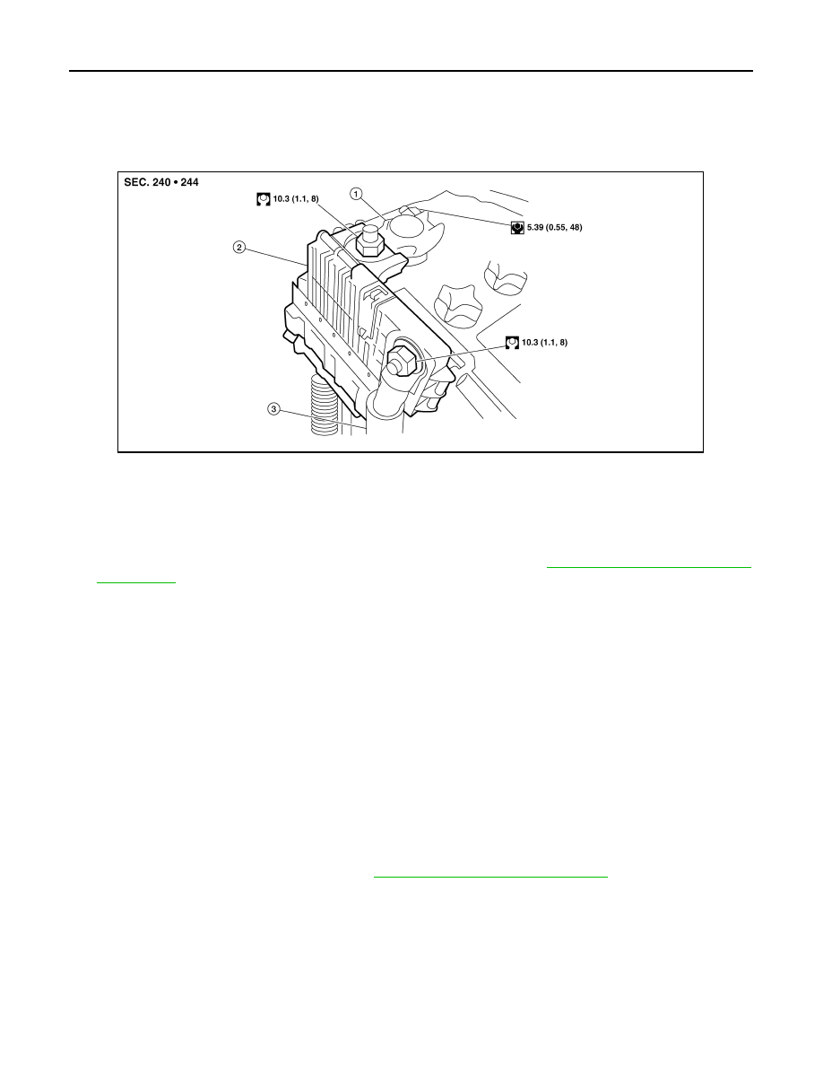
Exploded View
INFOID:0000000010119405
Removal and Installation
INFOID:0000000010119406
REMOVAL
1. Disconnect the 12V battery cable from the negative terminal. Refer to
PG-6, "Precaution for Removing
CAUTION:
To prevent damage to the parts, disconnect the 12V battery cable from the negative terminal first.
2. Remove cover of 12V battery positive terminal.
3. Disconnect the 12V battery cable from the positive terminal.
4. Open cover of harness mounting nut.
5. Remove harness mounting nut and battery terminal with fusible link mounting nut.
6. Disconnect harness connector and remove battery terminal with fusible link.
INSTALLATION
Install in the reverse order of removal.
CAUTION:
To install the 12V battery, carefully read the following instructions.
• To prevent damage to the parts, connect the 12V battery cable to the positive terminal first.
• After connecting 12V battery cables, to securely supply 12V battery voltage, ensure that they are
tightly clamped to 12V battery terminals for good contact.
• To securely supply 12V battery voltage, check 12V battery terminal for poor connection caused by
corrosion.
Reset electronic systems as necessary. Refer to
PG-86, "Special Repair Requirement"
1. Positive terminal
2. Fusible link box (battery)
3. Positive cable
AWMIA1544ZZ