Content .. 1017 1018 1019 1020 ..
Nissan Leaf. Manual - part 1019
PG-88
< BASIC INSPECTION >
FUSIBLE LINK INSPECTION
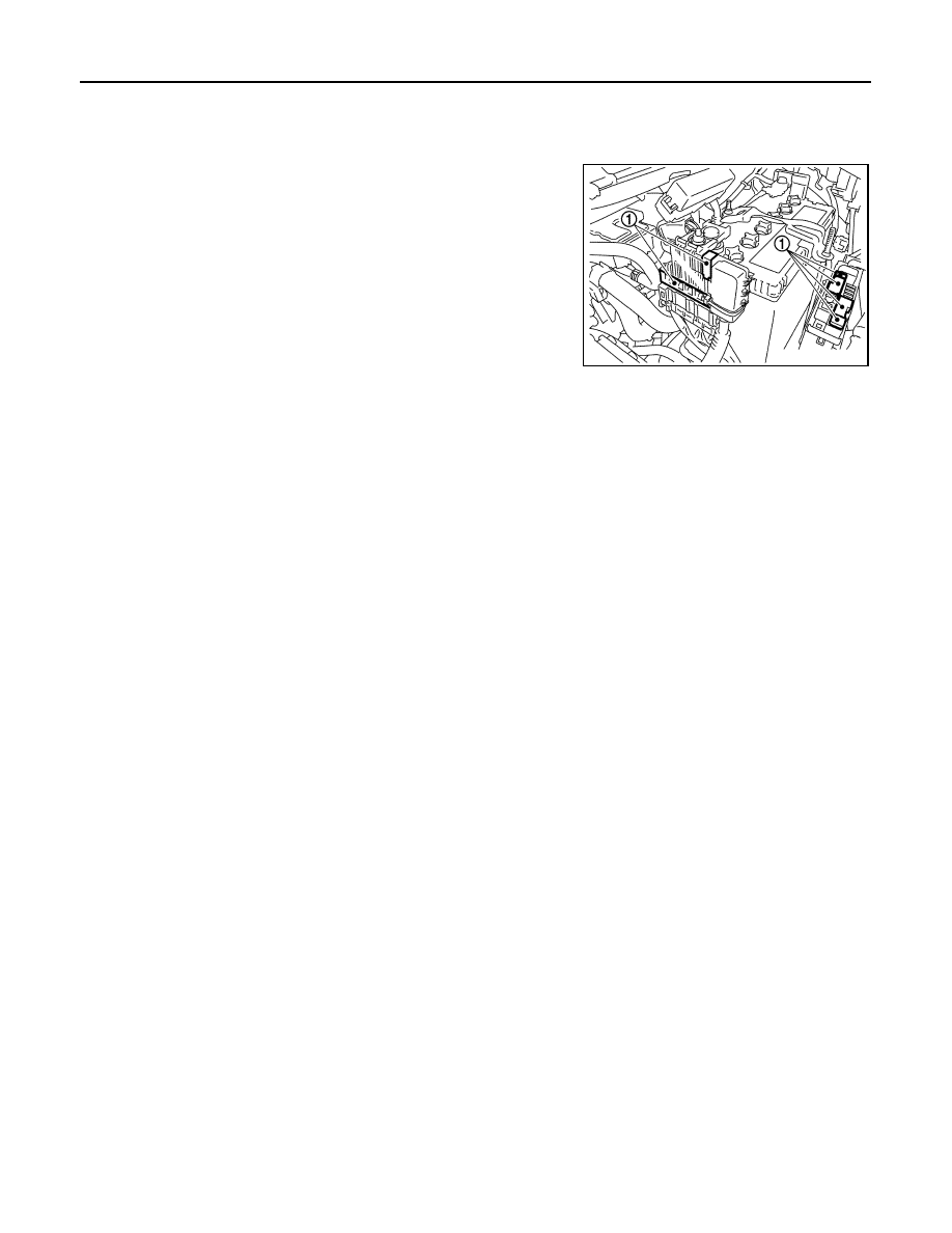
FUSIBLE LINK INSPECTION
How To Check
INFOID:0000000010119400
A melted fusible link can be detected either by visual inspection or by
feeling with finger tip. If its condition is questionable, use circuit
tester or test lamp.
CAUTION:
• If fusible link should melt, it is possible that critical circuit
(power supply or large current carrying circuit) is shorted. In
such a case, carefully check and eliminate cause of malfunc-
tion.
• Never wrap outside of fusible link with vinyl tape. Important:
Never let fusible link touch any other wiring harness, vinyl or
rubber parts.
1
:Fusible link
JSMIA0532ZZ