Nissan Leaf. Manual - part 78
AV
STEERING SWITCH
AV-303
< DTC/CIRCUIT DIAGNOSIS >
[NAVIGATION WITHOUT BOSE]
C
D
E
F
G
H
I
J
K
L
M
B
A
O
P
STEERING SWITCH
Diagnosis Procedure
INFOID:0000000010122569
Regarding Wiring Diagram information, refer to
.
1.
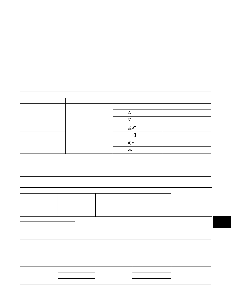
CHECK STEERING WHEEL AUDIO CONTROL SWITCH RESISTANCE
1. Turn power switch OFF.
2. Disconnect combination switch connector M112.
3. Check resistance between the terminals of combination switch connector M112.
Is the inspection result normal?
YES
>> GO TO 2.
NO
>> Replace steering switches. Refer to
AV-327, "Removal and Installation"
.
2.
CHECK COMBINATION SWITCH
Check continuity between combination switch connectors M112 and M92.
Is the inspection result normal?
YES
>> GO TO 3.
NO
>> Replace spiral cable. Refer to
SR-23, "Removal and Installation"
3.
CHECK HARNESS BETWEEN COMBINATION SWITCH AND AV CONTROL UNIT
1. Disconnect AV control unit connector M95.
2. Check continuity between combination switch connector M92 and AV control unit connector M95.
Combination switch connector M112
Condition
Resistance
Ω
(Approx.)
Terminal
Terminal
14
17
Depress SOURCE switch.
1
Depress
switch.
121
Depress
switch.
321
Depress
switch.
723
15
Depress
switch.
1
Depress
switch.
121
Depress
switch.
321
Combination switch
Continuity
Connector
Terminal
Connector
Terminal
M112
14
M92
24
Yes
15
31
17
33
Combination switch
AV control unit
Continuity
Connector
Terminal
Connector
Terminal
M92
24
M95
6
Yes
31
16
33
15