Nissan Leaf. Manual - part 76
AV
TWEETER
AV-295
< DTC/CIRCUIT DIAGNOSIS >
[NAVIGATION WITHOUT BOSE]
C
D
E
F
G
H
I
J
K
L
M
B
A
O
P
Is the inspection result normal?
YES
>> Replace tweeter. Refer to
AV-321, "Removal and Installation"
NO
>> Replace AV control unit. Refer to
AV-318, "Removal and Installation"
.
2
3
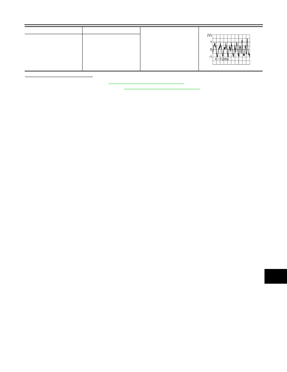
Audio signal output
11
12
SKIB3609E