Nissan Leaf. Manual - part 77


  Index      Nissan     Nissan Leaf (2011-2014 year) - Service and Repair Manual


Search            


Content   ..  75  76  77  78   ..


Nissan Leaf. Manual - part 77


AV

CAMERA IMAGE SIGNAL CIRCUIT

AV-299

< DTC/CIRCUIT DIAGNOSIS >

[NAVIGATION WITHOUT BOSE]

C

D

E

F

G

H

I

J

K

L

M

B

A

O

P

4.

CHECK CAMERA IMAGE SIGNAL CIRCUIT CONTINUITY

1. Turn power switch OFF.

2. Disconnect AV control unit connector M96 and rear view camera connector.

3. Check continuity between AV control unit connector M96 and rear view camera connector D556.

4. Check continuity between AV control unit connector M96 and ground.

Is inspection result normal?

YES

>> GO TO 5.

NO

>> Repair or replace harness or connectors.

5.

CHECK CAMERA GROUND CIRCUIT CONTINUITY

Check continuity between AV control unit connector M96 and rear view camera connector D556.

Is inspection result normal?

YES

>> GO TO 6.

NO

>> Repair or replace harness or connectors.

6.

CHECK CAMERA IMAGE SIGNAL

1. Connect AV control unit connector M96 and rear view camera connector.

2. Turn power switch ON.

3. Shift the selector lever to “R”.

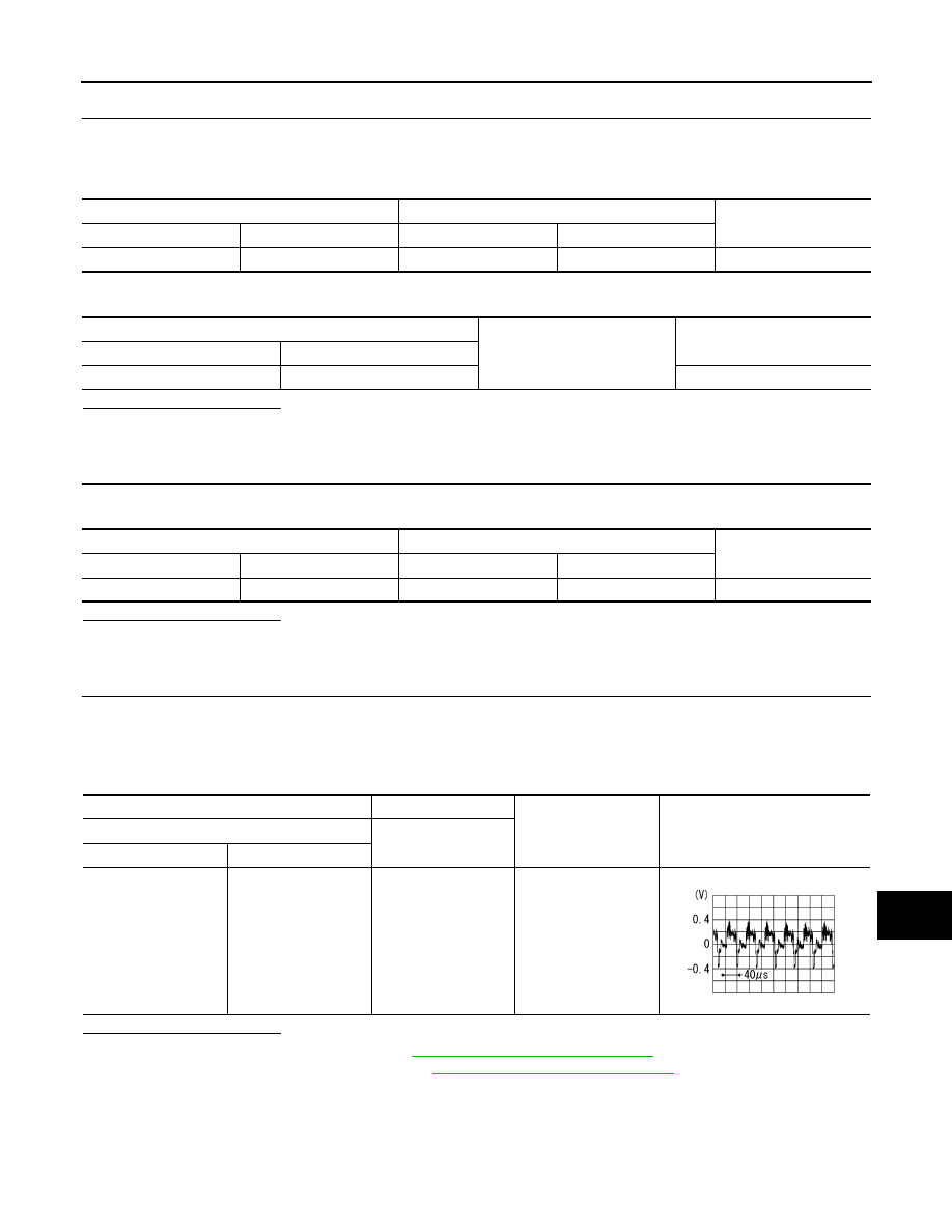
4. Check signal between AV control unit connector M96 and ground.

Is inspection result normal?

YES

>> Replace AV control unit. Refer to 

AV-69, "Removal and Installation"

.

NO

>> Replace rear view camera. Refer to 

AV-77, "Removal and Installation"

.

AV control unit

Rear view camera

Continuity

Connector

Terminal

Connector

Terminal

M96

40

D556

3

Yes

AV control unit

Ground

Continuity

Connector

Terminal

M96

40

No

AV control unit

Rear view camera

Continuity

Connector

Terminal

Connector

Terminal

M96

59

D556

2

Yes

AV control unit

Ground

Condition

Reference value

(+)

(

−)

Connector

Terminal

M96

40

Camera image dis-

played.

SKIB2251J

AV-300

< DTC/CIRCUIT DIAGNOSIS >

[NAVIGATION WITHOUT BOSE]

AUXILIARY INPUT JACK

AUXILIARY INPUT JACK

Diagnosis Procedure

INFOID:0000000010122567

Regarding Wiring Diagram information, refer to 

AV-255, "Wiring Diagram"

.

1.

CHECK AUXILIARY INPUT JACK HARNESS CONTINUITY

1. Turn power switch OFF.

2. Disconnect audio unit connector M96 and auxiliary input jack connector M52.

3. Check continuity between audio unit connector M96 and auxiliary input jack connector M52.

4. Check continuity between audio unit connector M96 and ground.

Is the inspection result normal?

YES

>> Replace the auxiliary input jack. Refer to 

AV-328, "Removal and Installation"

.

NO

>> Repair or replace harness or connectors.

Audio unit

Auxiliary input jack

Continuity

Connector

Terminal

Connector

Terminal

M96

36

M52

1

Yes

55

2

35

4

Audio unit

Continuity

Connector

Terminal

M96

35

Ground

No

55

AV

MICROPHONE SIGNAL CIRCUIT

AV-301

< DTC/CIRCUIT DIAGNOSIS >

[NAVIGATION WITHOUT BOSE]

C

D

E

F

G

H

I

J

K

L

M

B

A

O

P

MICROPHONE SIGNAL CIRCUIT

Diagnosis Procedure

INFOID:0000000010122568

Regarding Wiring Diagram information, refer to 

AV-255, "Wiring Diagram"

.

1.

CHECK MICROPHONE SIGNAL CIRCUIT CONTINUITY

1. Turn power switch OFF.

2. Disconnect AV control unit connector M96 and microphone connector R3.

3. Check continuity between AV control unit connector M96 and microphone connector R3.

4. Check continuity between AV control unit connector M961 and ground.

Is inspection result normal?

YES

>> GO TO 2.

NO

>> Repair or replace harness or connectors.

2.

CHECK MICROPHONE VCC VOLTAGE

1. Connect AV control unit connector M96.

2. Turn power switch ON.

3. Check voltage between terminals of AV control unit connector M96.

Is the inspection result normal?

YES

>> GO TO 3.

NO

>> Replace AV control unit. Refer to 

AV-318, "Removal and Installation"

.

3.

CHECK MICROPHONE SIGNAL 

1. Connect microphone connector.

2. Check signal between terminals of AV control unit connector M96.

AV control unit

Microphone

Continuity

Connector

Terminal

Connector

Terminal

M96

34

R3

4

Yes

53

1

54

2

AV control unit

Ground

Continuity

Connector

Terminal

M96

34

No

53

54

AV control unit connector M96

Voltage

(Approx.)

(+)

(

−)

Terminal

Terminal

34

54

5.0 V

AV-302

< DTC/CIRCUIT DIAGNOSIS >

[NAVIGATION WITHOUT BOSE]

MICROPHONE SIGNAL CIRCUIT

Is the inspection result normal?

YES

>> Replace AV control unit. Refer to 

AV-318, "Removal and Installation"

.

NO

>> Replace microphone. Refer to 

AV-324, "Removal and Installation"

.

AV control unit connector M96

Condition

Reference value

(+)

(

−)

Terminal

Terminal

53

54

Speak into microphone.

PKIB5037J


Content   ..  75  76  77  78   ..