Nissan Leaf. Manual - part 57


  Index      Nissan     Nissan Leaf (2011-2014 year) - Service and Repair Manual


Search            


Content   ..  55  56  57  58   ..


Nissan Leaf. Manual - part 57


AV

COMPONENT PARTS

AV-219

< SYSTEM DESCRIPTION >

[NAVIGATION WITHOUT BOSE]

C

D

E

F

G

H

I

J

K

L

M

B

A

O

P

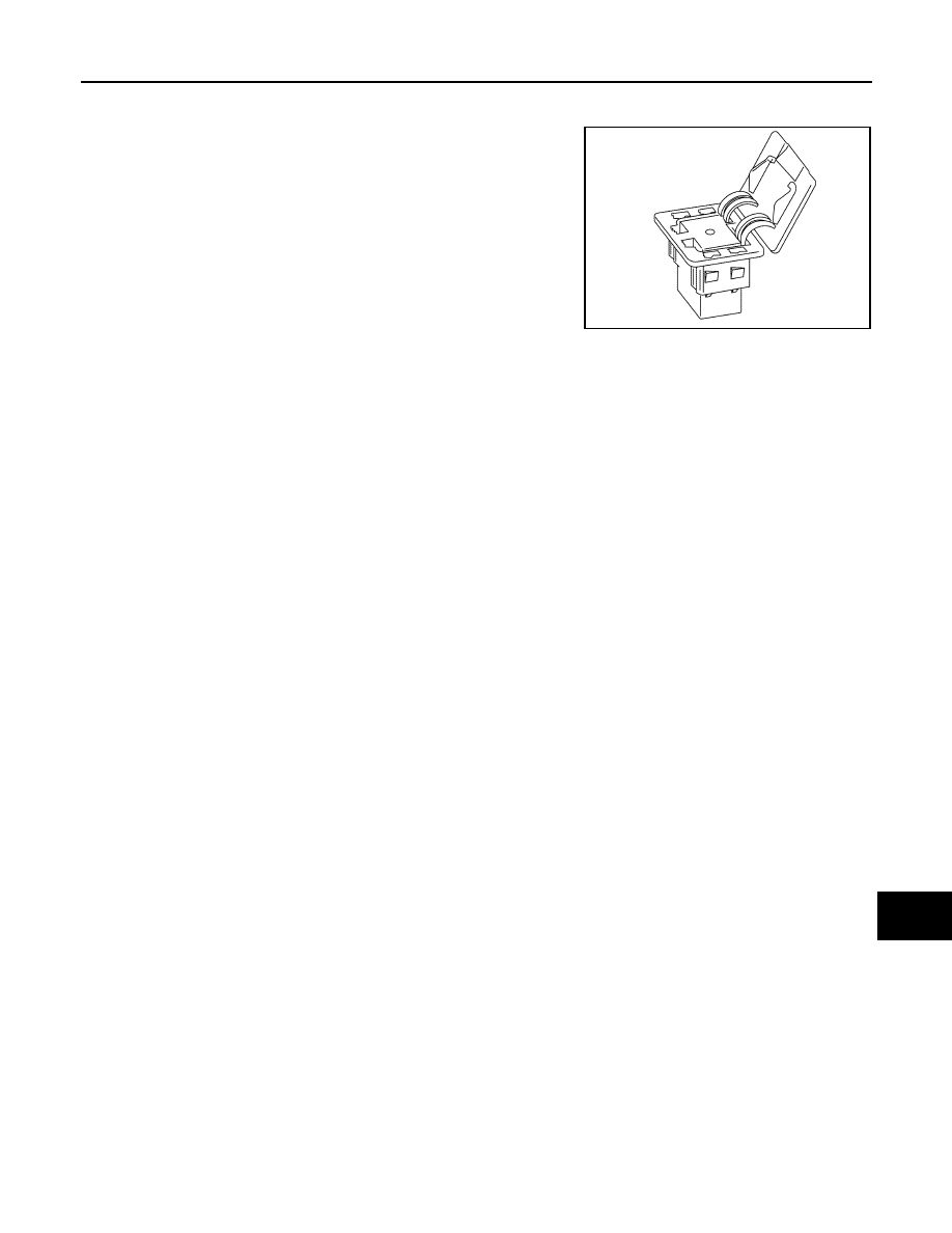
Auxiliary Input Jack

INFOID:0000000010122517

• AUX jack is installed at the lower right of the instrument panel.

• Connection to an external audio device can provide sound output.

NOTE:

When connected to monaural mini-jack plug cable, sound may not

be output.

SD Card

INFOID:0000000010122518

• Map data is memorized in an 8 GB SDHC

*

 card.

• Map data is sent to the AV control unit from the SD slot.

NOTE:

*SDHC: Abbreviation of SD High-Capacity. It is the upper level standard of the SD memory card. A large quan-

tity of data can be memorized, and the transfer speed of data is high.

External input terminal for connection 

φ3.5 mm stereo mini-jack 

JSNIA3792ZZ

AV-220

< SYSTEM DESCRIPTION >

[NAVIGATION WITHOUT BOSE]

SYSTEM

SYSTEM

MULTI AV SYSTEM
MULTI AV SYSTEM : System Diagram

INFOID:0000000010122519

CAN communication

AV control unit Input Signal

AWNIA3470GB

Transmit unit

Signal name

Combination meter

Odometer signal

A/C OFF average electricity consumption for driving range signal

A/C ON average electricity consumption for driving range signal

Driving range difference signal

AV

SYSTEM

AV-221

< SYSTEM DESCRIPTION >

[NAVIGATION WITHOUT BOSE]

C

D

E

F

G

H

I

J

K

L

M

B

A

O

P

TCU Input Signal

MULTI AV SYSTEM : System Description

INFOID:0000000010122520

• AV control unit is connected to the following parts. It performs power supply, signal input and communica-

tion, and it controls the multi-AV system.

- GPS antenna

- Radio antenna (radio antenna amplifier) 

- Rear view camera

- USB connector

- Auxiliary input jack

- BCM

- VCM

- Combination meter

- Steering switch

- Multifunction switch

- Microphone

- TCU

- Speakers 

- Vehicle signals (reverse signal, vehicle speed signal and illumination signal)

• Data of external device connected to the USB connector is played and transferred.

• When the selector lever is placed in R (reverse), power is supplied to the rear view camera. The camera

image signal supplied by the rear view camera is input to the AV control unit. The AV control unit displays the

rear view camera image on the display. 

• Dimming signal is input from BCM to adjust the brightness of the display.

VCM

A/C consumption power status display signal

A/C consumption signal

Current motor power signal

ECO tree signal

Li-ion battery charging data signal

Others consumption signal

Pre-A/C priority signal

Pre-A/C timer signal

Remaining time to charge completion (200 V) signal

Remaining time to charge completion (100 V) signal

Traction motor consumption signal

VCM activation/deactivation command signal

VCM status signal

Transmit unit

Signal name

Transmit unit

Signal name

VCM

A/C expected consumption signal

Charge status signal

Pre-A/C status signal

Remaining time to charge completion (200 V) signal

Remaining time to charge completion (100 V) signal

VCM activation/deactivation command signal

VCM status signal

Li-ion battery available charge signal

Li-ion battery capacity signal

Li-battery gradual capacity loss signal

On board charger

AC input type signal

AV-222

< SYSTEM DESCRIPTION >

[NAVIGATION WITHOUT BOSE]

SYSTEM

COMMUNICATION SIGNAL

AV control unit is connected to TCU via USB communication, and it receives the Telematics information

received by TCU and gives the display and sound output. Telematics operation signals and sound signals are

also sent to TCU.

Auto light adjustment function 

Auto light adjustment function automatically dims/brightens the display according to the ambient light when the

lighting switch is in the 1st or 2nd position. Whether or not the display is dimmed when the lighting switch is in

the 1st position or 2nd position is determined by the output condition of the dimming signal output from the

BCM to the AV control unit. Even if the lighting switch is in the 1st position or 2nd position, the display may not

be dimmed depending on the ambient light sensed by the auto light sensor. For details, refer to 

INL-11, "ILLU-

MINATION CONTROL SYSTEM : System Description"

.

CAN COMMUNICATION

• AV control unit is connected via CAN communication, receives data signal from VCM and combination

meter, and indicates power consumption information, etc. on the display based on the information obtained.

• The AV control unit, which has the vehicle setting function, transmits and receives data on vehicle setting

condition via CAN communication with the BCM.

• AV control unit receives and sends signals necessary for timer charge and A/C-heater timer operation with

VCM via CAN communication.

Energy Flow Display Function 

The AV control unit receives data signals from the VCM and combination meter via CAN communication and

computes each value using the obtained information to display it.

Vehicle Setting Function

The AV control unit transmits and receives data signals via CAN communication with the BCM, allowing the

following vehicle settings.

• To turn on the automatic interior room lamp (ON/OFF) when the door is unlocked

• To adjust the auto light sensitivity (+/

−)

• To operate the intermittent wiper linked with the vehicle speed (ON/OFF)

• Vehicle setting initialization 

NOTE:

The setting items vary depending on the vehicle specification

TYPE OF VOICE SIGNAL

Reception Voice Signal

• Hands-free phone reception voice is output from the cellular phone through the AV control unit to the front

speaker via Bluetooth

®

 communication.

• If the hands-free phone is used while the audio is ON and/or the voice guidance is being output, these

sounds are muted and only the reception voice is output.

Speech Sound Signal

Hands-free phone speech sound is transmitted from the microphone via the AV control unit and Bluetooth

®

communication to the cellular phone.

Display function

Receiving signal (transmit unit)

Display method

Instantaneous power 
consumption display

• Battery consumption monitor signal 

(VCM) 

• Vehicle speed signal (combination 

meter)

Computes the instantaneous power consumption using the vehicle 
speed and battery consumption monitor signals, and displays the in-
stantaneous power consumption bar.

Possible driving dis-
tance display

• Possible driving distance signal

(Combination meter)

Displays a possible driving distance, based on a possible driving 
distance signal. When the meter indication of a possible driving dis-
tance is “----”, it is displayed by “

”on the NAVI screen.

Data is retained even with the power switch OFF.

Average power con-
sumption display

• Battery consumption monitor signal 

(VCM) 

• Vehicle speed signal (combination 

meter)

Computes the average power consumption using the battery con-
sumption monitor and vehicle speed signals, and displays it.
The average power consumption is displayed only when 30 sec-
onds have elapsed and the vehicle has been driven 500 m after the 
average power consumption was reset.
Data is retained even with the power switch OFF.


Content   ..  55  56  57  58   ..