Nissan Leaf. Manual - part 56
 

  Index      Nissan     Nissan Leaf (2011-2014 year) - Service and Repair Manual


Search            


Content   ..  54  55  56  57   ..


Nissan Leaf. Manual - part 56


AV

COMPONENT PARTS

AV-215

< SYSTEM DESCRIPTION >

[NAVIGATION WITHOUT BOSE]

C

D

E

F

G

H

I

J

K

L

M

B

A

O

P

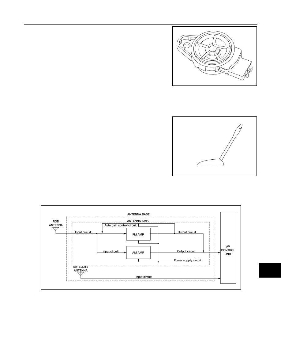
• Sound signal is input from the AV control unit to output high range

sounds.

Radio Antenna and Antenna Feeder

INFOID:0000000010122509

RADIO ANTENNA

Rod Antenna

A rod antenna is installed to the rear center of the roof.

Antenna Base

• To obtain sufficient reception sensitivity, an antenna amplifier is built into the antenna base.

• Power of the antenna amplifier is supplied from the AV control unit.

• The radio signal received by the rod antenna is input to the antenna base and the antenna signal is amplified

and sent to the AV control unit.

Satellite radio Antenna

• Receives satellite radio waves and outputs it to AV control unit.

Antenna circuit

JSNIA3849ZZ

ALNIA1616ZZ

AWNIA3469GB

AV-216

< SYSTEM DESCRIPTION >

[NAVIGATION WITHOUT BOSE]

COMPONENT PARTS

: Indicates that the part is connected at points with same symbol in actual vehicle.

JSNIA3555GB

AV

COMPONENT PARTS

AV-217

< SYSTEM DESCRIPTION >

[NAVIGATION WITHOUT BOSE]

C

D

E

F

G

H

I

J

K

L

M

B

A

O

P

Steering Switch

INFOID:0000000010122510

• Hands-free phone, possible driving distance display, voice control,

and audio operations can be performed.

• This switch is connected to the AV control unit, and the switch

operation signal is transmitted to the AV control unit via voltage

multiplex communication.

Multifunction Switch

INFOID:0000000010122511

• Audio, navigation, Telematics, etc. can be controlled.

• Switch operation signals are input to the AV control unit via AV

communication.

TCU

INFOID:0000000010122512

• TCU is installed on the lower right of the instrument panel.

• A radio communication terminal is built into the unit, and data is

sent and received in SMS and packet communication with the NIS-

SAN CARWINGS Data Center through the TEL antenna.

• VIN information necessary for the Telematics service is memo-

rized.

GPS Antenna

INFOID:0000000010122513

• GPS antenna is installed in the instrument panel.

• Power is supplied from the AV control unit.

• This antenna amplifies radio waves received from the GPS satel-

lite and transmits the GPS signal to the AV control unit.

NOTE:

An object on the instrument panel may cause the reception sensitiv-

ity to be decreased.

JSNIA3619ZZ

JSNIA3620ZZ

JSNIA3622ZZ

JSNIA3303ZZ

AV-218

< SYSTEM DESCRIPTION >

[NAVIGATION WITHOUT BOSE]

COMPONENT PARTS

USB Connector

INFOID:0000000010122514

• USB connector is installed on the lower left side of the instrument

panel.

• iPod

®

 and USB memory can be connected to the AV control unit.

Microphone

INFOID:0000000010122515

• The voice control/TEL microphone is installed on the right side of

the map lamp assembly.

• The power is supplied from the AV control unit to the microphone,

transmitting sound signals to the AV control unit at the voice con-

trol or during hands-free phone communication.

TEL Antenna

INFOID:0000000010122516

• The TEL antenna is installed in the instrument panel.

• Power is supplied with TCU activated.

Rear View Camera

INFOID:0000000010546195

• The rear camera is installed to the back door finisher. 

• Power for the camera is supplied from the AV control unit, and the

image signal at the rear of the vehicle is sent back to the AV control

unit. 

JPNIA1447ZZ

JPNIA1448ZZ

JSNIA3624ZZ

JSNIA5396ZZ


Content   ..  54  55  56  57   ..