Nissan Primera P11. Manual - part 457
NOTICE
Trouble diagnoses indicates work procedures required to diag-
nose problems effectively. Observe the following instructions
before diagnosing.
1) Before performing trouble diagnoses, read the “Prelimi-
nary Check”, the “Symptom Chart” or the “Work Flow”.
2) After repairs, re-check that the problem has been com-
pletely eliminated.
3) Refer to Component Parts and Harness Connector Loca-
tion for the Systems described in each section for
identification/location of components and harness con-
nectors.
4) Refer to the Circuit Diagram for Quick Pinpoint Check.
If you need to check circuit continuity between harness
connectors in more detail, such as when a sub-harness
is used, refer to Wiring Diagram in each individual sec-
tion and Harness Layout in EL section for identification
of harness connectors.
5) When checking circuit continuity, ignition switch should
be in the “LOCK” position.
6) Before checking voltage at connectors, check battery
voltage.
7) After accomplishing the Diagnostic Procedures and
Electrical Components Inspection, make sure that all
harness connectors are reconnected as they were.
How to Follow Test Groups in Trouble
Diagnoses
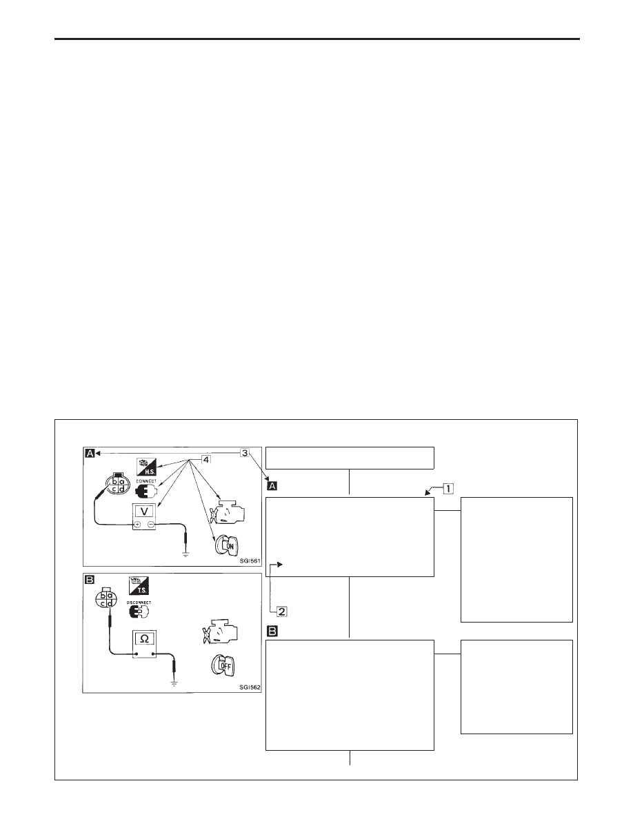
Example Type A
SGI800-C
INSPECTION START
CHECK POWER SUPPLY.
1) Turn ignition switch to “ON” posi-
tion.
2) Check voltage between terminal
p
b
and ground.
Battery voltage should exist
OK
E
NG
Check the following
items.
1) Harness continuity
between camshaft
position sensor and
battery
2) Engine relay-1
3) “BR” fusible link
4) Power source for
ECM
5) Ignition switch
CHECK GROUND CIRCUIT.
1) Turn ignition switch to “OFF” posi-
tion.
2) Disconnect camshaft position sen-
sor harness connector.
3) Check resistance between termi-
nal
p
d
and ground.
Resistance:
Approximately 0
Ω
OK
E
NG
Check the following
items.
1) Harness continuity
between camshaft
position sensor and
ground
2) Ground circuit for
ECM
H
H
H
HOW TO FOLLOW TROUBLE DIAGNOSES
GI-35