Nissan Primera P11. Manual - part 455


  Index      Nissan     Nissan Primera P11 (2001 year) - Service and Repair Manual


Search            


Content   ..  453  454  455  456   ..


Nissan Primera P11. Manual - part 455


Engine compartment

There are several reasons a vehicle or engine vibration could
cause an electrical complaint. Some of the things to check for
are:

Connectors not fully seated.

Wiring harness not long enough and is being stressed due
to engine vibrations or rocking.

Wires laying across brackets or moving components.

Loose, dirty or corroded ground wires.

Wires routed too close to hot components.

To inspect components under the hood, start by verifying the
integrity of ground connections. (Refer to GROUND INSPEC-
TION described later.) First check that the system is properly
grounded. Then check for loose connection by gently shaking
the wiring or components as previously explained. Using the
wiring diagrams inspect the wiring for continuity.

Behind the instrument panel

An improperly routed or improperly clamped harness can
become pinched during accessory installation. Vehicle vibration
can aggravate a harness which is routed along a bracket or near
a screw.

Under seating areas

An unclamped or loose harness can cause wiring to be pinched
by seat components (such as slide guides) during vehicle vibra-
tion. If the wiring runs under seating areas, inspect wire routing
for possible damage or pinching.
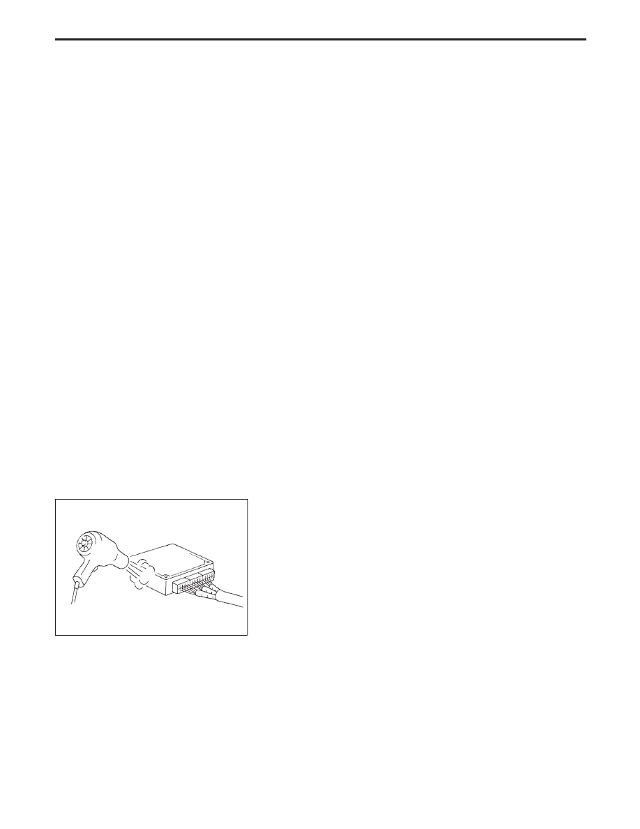
HEAT SENSITIVE

The owner’s problem may occur during hot weather or after car
has sat for a short time. In such cases you will want to check for
a heat sensitive condition.
To determine if an electrical component is heat sensitive, heat
the component with a heat gun or equivalent.
Do not heat components above 60°C (140°F). If incident
occurs while heating the unit, either replace or properly insulate
the component.

SGI842

Heating test

Heat gun

Do not heat above 60°C (140°F).

HOW TO PERFORM EFFICIENT DIAGNOSIS

FOR AN ELECTRICAL INCIDENT

Incident Simulation Tests (Cont’d)

GI-27

FREEZING

The customer may indicate the incident goes away after the car
warms up (winter time). The cause could be related to water
freezing somewhere in the wiring/electrical system.
There are two methods to check for this. The first is to arrange
for the owner to leave his car overnight. Make sure it will get cold
enough to demonstrate his complaint. Leave the car parked out-
side overnight. In the morning, do a quick and thorough diagno-
sis of those electrical components which could be affected.
The second method is to put the suspect component into a
freezer long enough for any water to freeze. Reinstall the part
into the car and check for the reoccurrence of the incident. If it
occurs, repair or replace the component.

WATER INTRUSION

The incident may occur only during high humidity or in rainy/
snowy weather. In such cases the incident could be caused by
water intrusion on an electrical part. This can be simulated by
soaking the car or running it through a car wash.
Do not spray water directly on any electrical components.

ELECTRICAL LOAD

The incident may be electrical load sensitive. Perform diagnosis
with all accessories (including A/C, rear window defogger, radio,
fog lamps) turned on.

COLD OR HOT START UP

On some occasions an electrical incident may occur only when
the car is started cold. Or it may occur when the car is restarted
hot shortly after being turned off. In these cases you may have
to keep the car overnight to make a proper diagnosis.

SGI843

Freezing test

Water in
connector

Solenoid

Short

SGI844

Water intrusion test

SGI845

Electrical load test

“ON”

Rear win-
dow defog-
ger

Light switch

A/C

HOW TO PERFORM EFFICIENT DIAGNOSIS

FOR AN ELECTRICAL INCIDENT

Incident Simulation Tests (Cont’d)

GI-28

Circuit Inspection

INTRODUCTION

In general, testing electrical circuits is an easy task if it is approached in a logical and organized method.
Before beginning it is important to have all available information on the system to be tested. Also, get a
thorough understanding of system operation. Then you will be able to use the appropriate equipment and
follow the correct test procedure.
You may have to simulate vehicle vibrations while testing electrical components. Gently shake the wiring
harness or electrical component to do this.

OPEN

A circuit is open when there is no continuity through a section of the circuit.

SHORT

There are two types of shorts.

SHORT CIRCUIT

When a circuit contacts another circuit and causes the
normal resistance to change.

SHORT TO GROUND

When a circuit contacts a ground source and grounds the
circuit.

TESTING FOR “OPENS” IN THE CIRCUIT

Before you begin to diagnose and test the system, you should rough sketch a schematic of the system. This
will help you to logically walk through the diagnosis process. Drawing the sketch will also reinforce your
working knowledge of the system.

Continuity check method

The continuity check is used to find an open in the circuit. The Digital Multimeter (DMM) set on the resis-
tance function will indicate an open circuit as over limit (OL, no beep tone or no ohms symbol). Make sure
to always start with the DMM at the highest resistance level.
To help in understanding the diagnosis of open circuits please refer to the schematic above.

1. Disconnect the battery negative cable.
2. Start at one end of the circuit and work your way to the other end. (At the fuse block in this example)
3. Connect one probe of the DMM to the fuse block terminal on the load side.
4. Connect the other probe to the fuse block (power) side of SW1. Little or no resistance will indicate that

portion of the circuit has good continuity. If there were an open in the circuit, the DMM would indicate
an over limit or infinite resistance condition. (point A)

5. Connect the probes between SW1 and the relay. Little or no resistance will indicate that portion of the

circuit has good continuity. If there were an open in the circuit, the DMM would indicate an over limit or
infinite resistance condition. (point B)

6. Connect the probes between the relay and the solenoid. Little or no resistance will indicate that portion

of the circuit has good continuity. If there were an open in the circuit, the DMM would indicate an over
limit or infinite resistance condition. (point C)

Any circuit can be diagnosed using the approach in the above example.

SGI846

Inspection for opens

FUSE BLOCK

B+

SIDE

DMM

(Voltage check)

SW1

N.C. RELAY

SOLENOID

OPEN

A

OPEN

B

OPEN

C

DMM

DMM

SW2

(Continuity check)

HOW TO PERFORM EFFICIENT DIAGNOSIS

FOR AN ELECTRICAL INCIDENT

GI-29

Voltage check method

To help in understanding the diagnosis of open circuits please refer to the previous schematic.
In any powered circuit, an open can be found by methodically checking the system for the presence of volt-
age. This is done by switching the DMM to the voltage function.
1. Connect one probe of the DMM to a known good ground.
2. Begin probing at one end of the circuit and work your way to the other end.
3. With SW1 open, probe at SW1 to check for voltage.

voltage;

open is further down the circuit than SW1.

no voltage;

open is between fuse block and SW1 (point A).

4. Close SW1 and probe at relay.

voltage;

open is further down the circuit than the relay.

no voltage;

open is between SW1 and relay (point B).

5. Close the relay and probe at the solenoid.

voltage;

open is further down the circuit than the solenoid.

no voltage;

open is between relay and solenoid (point C).

Any powered circuit can be diagnosed using the approach in the above example.

TESTING FOR “SHORTS” IN THE CIRCUIT

To simplify the discussion of shorts in the system please refer to the schematic below.

Resistance check method

1. Disconnect the battery negative cable and remove the blown fuse.
2. Disconnect all loads (SW1 open, relay disconnected and solenoid disconnected) powered through the

fuse.

3. Connect one probe of the ohmmeter to the load side of the fuse terminal. Connect the other probe to a

known good ground.

4. With SW1 open, check for continuity.

continuity;

short is between fuse terminal and SW1 (point A).

no continuity;

short is further down the circuit than SW1.

5. Close SW1 and disconnect the relay. Put probes at the load side of fuse terminal and a known good

ground. Then, check for continuity.
continuity;

short is between SW1 and the relay (point B).

no continuity;

short is further down the circuit than the relay.

6. Close SW1 and jump the relay contacts with jumper wire. Put probes at the load side of fuse terminal

and a known good ground. Then, check for continuity.
continuity;

short is between relay and solenoid (point C).

no continuity;

check solenoid, retrace steps.

SGI847

Inspection for shorts

IGN “ON”
OR “START”

B+

SIDE

FUSE BLOCK

DMM

(Resistance check)

SW1

RELAY

SOLENOID

SHORT

A

SHORT

B

SHORT

C

DMM

(Voltage check)

SW2

HOW TO PERFORM EFFICIENT DIAGNOSIS

FOR AN ELECTRICAL INCIDENT

Circuit Inspection (Cont’d)

GI-30


Content   ..  453  454  455  456   ..